Rosemount Model 1195/ProPlate/Mass ProPlate
3-2
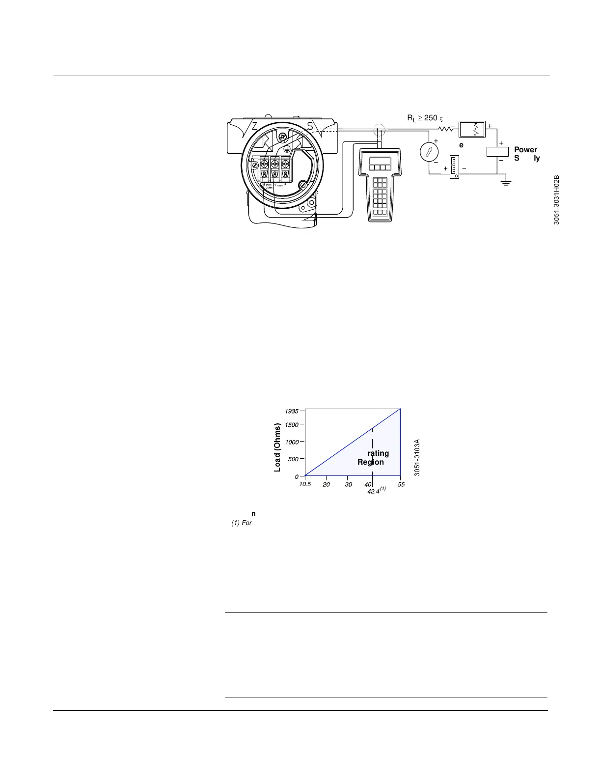
Figure 3-1. Field Hook-up
(4–20 mA Flowmeters)
Electrical Considerations The signal terminals are located in a compartment of the electronics
housing separate from the ProPlate electronics. Connections for the
HART-based communicator are located below the signal terminals. The
Model 272 Field Calibrator can be connected at the signal terminals to
provide power to the electronics temporarily for calibration or
diagnostic purposes. Otherwise, the calibrator may be attached to the
test connections on the terminal block of the electronics for indication
purposes. Figure 3-2 illustrates power supply load limitations for the
ProPlate.
Figure 3-2. Power Supply Load
Limitations.
Power Supply (4–20mA
electronics)
The dc power supply should provide power with less than 2 percent
ripple. The total resistance load is the sum of the resistance of the
signal leads and the load resistance of the controller, indicator, and
related pieces. Note that the resistance of intrinsic safety barriers, if
used, must be included.
NOTE
A minimum loop resistance of 250 ohms is required to communicate with a
HART-based communicator. With 250 ohms of loop resistance, the ProPlate
will require a minimum of 15.5 volts to output 20 mA. If a single power
supply is used to power more than one ProPlate, the power supply used, and
circuitry common to the ProPlates, should not have more than 20 ohms of
impedance at 1200Hz.
CAUTION
Do not use inductive-based transient protectors.
Signal point may be grounded at any
point or left ungrounded.
+
%
R
L
250
V
Power
Supply
Curre
Communication requires a minimum loop resistance of 250 ohms.
/
R
D
G
2
K
P
V
$
Voltage (V dc)
Operating
Region
(1) For CSA approval, power supply must not exceed 42.4 V.

 Loading...