3-5
MASS PROPLATE
FLOWMETER
This section provides electrical considerations and ProPlate field
wiring instructions.
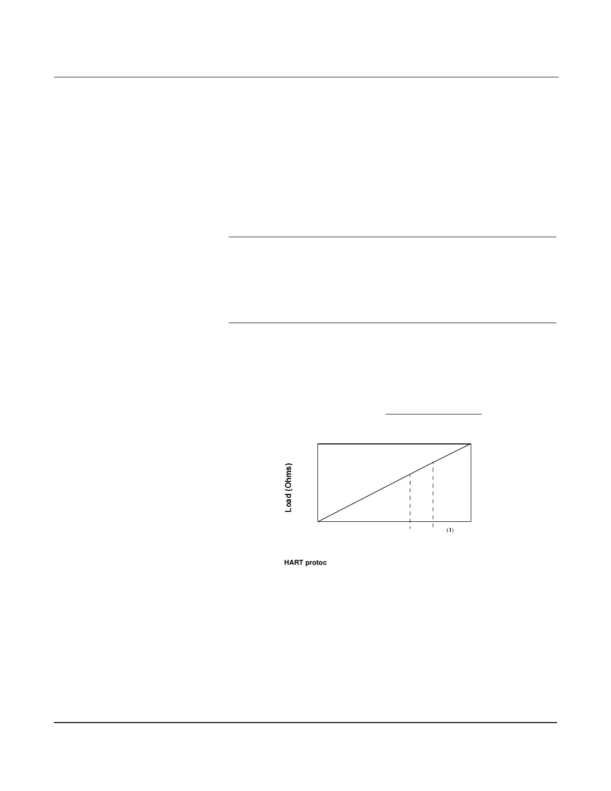
Electrical Considerations The signal terminals are located in a compartment of the electronics
housing separate from the electronics. Figure 3-3 illustrates power
supply load limitations for the Mass ProPlate.
Power Supply The dc power supply should provide power with less than 2% ripple.
The total resistance load is the sum of the resistance of the signal leads
and the load resistance of the controller, indicator, and related pieces.
Note that the resistance of intrinsic safety barriers, if used, must be
included.
NOTE
A loop resistance between 250-1100 ohms inclusive is required to
communicate with a personal computer. With 250 ohms of loop
resistance, a power supply voltage of at least 16.5 V dc is required.
(1)
If
a single power supply is used to power more than one Mass ProPlate,
the power supply used, and circuitry common to the Mass ProPlates,
should not have more than 20 ohms of impedance at 1200 Hz.
Figure 3-3. Mass ProPlate Power
Supply Load Limitations.
Load Limitations
Loop resistance is determined by the voltage level of the external power
supply, as described below:
HAZARDOUS LOCATIONS The Mass ProPlate has an explosion-proof housing and circuitry
suitable for intrinsically safe and non-incendive operation. Individual
Mass ProPlates are clearly marked with a tag indicating the
certifications they carry. See Section : Specifications and Reference
Data for specific approval categories.
(1) Quick troubleshooting check: There must be at least 11.0 V DC across the Mass Pro-
Plate electronics terminals.
2000
0
11.0
4–20 mA dc
55
/
R
D
G
2
K
P
V
HART protocol communication requires a loop resistance value
between 250–1100 ohms, inclusive.
Max. Loop Resistance = Power Supply Voltage–11.0
0.022
Power Supply Voltage V dc
35
(1) For CSA approval, power supply must not exceed 42.4 V dc.
Operating Region
42.4 V
(1)

 Loading...