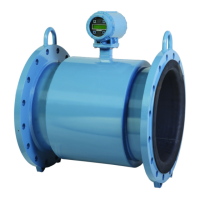
Rosemount Model 1195/ProPlate/Mass ProPlate
5-6
Wiring Diagrams (Field Hook-up)
The following diagrams illustrate wiring loops for a field hook-up with
a HART-based communicator.
Figure 5-3. Field Hook-up (4-20 mA
Flowmeters)
Review Configuration Data NOTE
Information and procedures in this section that make use of HART
Communicator fast key sequences assume that the flowmeter and
communicator are connected, powered, and operating correctly.
If you are not familiar with the HART Communicator or fast-key
sequences, refer to Appendix A: HART Communicator.
Before you place the flowmeter into operation, it is recommended that
you review the flowmeter configuration data that was set at the factory.
You should review the following configuration data: Flowmeter Model,
Type, Tag, Range, Date, Descriptor, Message, Minimum and Maximum
Sensor Limits, Minimum Span, Units, 4 and 20 mA points, Output
(linear or square root), Damping, Alarm Setting (high, low), Security
Setting (on, off), Local Keys (enabled, disabled), Integral Meter, Sensor
Fill, Isolator Material, Flange (type, material), O-Ring Material,
Drain/Vent, Remote Seal (type, fill fluid, isolator material, number),
Flowmeter S/N, Address, and Sensor S/N.
Check Output Before performing other flowmeter on-line operations, review the
digital output parameters to ensure that the flowmeter is operating
properly and is configured to the appropriate process variables.
6LJQDOSRLQWPD\EHJURXQGHGDWDQ\
SRLQWRUOHIWXQJURXQGHG
+
%
R
L
250
V
Power
Supply
&XUUHQW
0HWHU
&$87,21
'RQRWXVHLQGXFWLYHEDVHGWUDQVLHQWSURWHFWRUV
HART Comm. 1, 5

 Loading...