Loading...
Do you have a question about the Emerson Rosemount 1195 and is the answer not in the manual?
| Communication Protocol | HART |
|---|---|
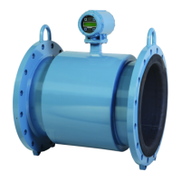
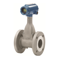
| Type | Differential Pressure Flow Meter |
| Output Signal | 4 to 20 mA |
| Power Supply | 10.5 to 45 VDC |
| Orifice Plate Type | Concentric, Eccentric, Segmental |
| Line Size | 1/2 in to 24 in |
| Material | Stainless Steel |
| Standard Compliance | ASME, ISO |
| Process Temperature Range | -40°C to 120°C (-40°F to 248°F) |
| Enclosure Rating | IP66 |
| Electrical Connection | 1/2 in NPT |
| Sensor Type | Differential Pressure |
| Measurement Range | Depends on orifice plate and line size |
Procedures and instructions may require special precautions to ensure personnel safety.
Provides installation, configuration, calibration, troubleshooting, and maintenance instructions.
Explains manual sections, provides a flowchart, and an installation checklist.
Describes orifice assembly installation into process piping with various connections.
Discusses transmitter and orifice assembly installation for accuracy and access.
Recommends a 3-valve bypass manifold for servicing without process flow interruption.
Details recommended upstream and downstream pipe lengths to minimize disturbance effects.
Explains connecting high pressure port to transmitter and positioning drain/vent plugs.
Recommends transmitter facing down to prevent air entrapment in liquid service.
Recommends transmitter facing up to prevent condensate entrapment in gas service.
Recommends transmitter facing down to prevent air entrapment in steam service.
Provides guidelines for using valves and fittings rated for service pressure and temperature.
Explains impulse piping for remote electronics and temperature considerations.
Lists tools and equipment for proper remote mount installation.
Lists specific tools required for remote mount installation.
Lists necessary supplies for remote mount installation.
Details recommended and alternate electronics locations for liquid service.
Details recommended and alternate electronics locations for gas service.
Specifies electronics must be installed below process piping for high temperature service.
Provides a procedure for installing bolts and torque specifications.
Illustrates wiring loops for field hook-up with a HART-based communicator.
Discusses signal terminals, HART communicator connections, and power supply load limitations.
Details DC power supply requirements and total resistance load considerations.
Advises on signal wiring practices to avoid interference and grounding points.
Outlines methods for grounding the ProPlate case according to codes.
Provides instructions for commissioning direct mounted models based on service type.
Refers to specific instructions for remote mounted ProPlate flowmeters.
Provides instructions for commissioning direct mounted ProPlates for liquid service.
Provides instructions for commissioning direct mounted ProPlates for gas service.
Provides instructions for commissioning direct mounted ProPlates for steam service.
Identifies manifold valves and their purpose before commissioning.
Details the procedure for checking the 'zero' calibration before exposing electronics.
Explains how to check for leaks after installation is complete.
Explains ProPlate's zero calibration is critical and affected by static pressure and ambient temp.
Provides a procedure to obtain a true zero at static or 'pipe' pressure.
Explains testing the flowmeter, loop, and configuration data before installation.
Discusses the ProPlate's automatic diagnostic routine and output behavior during failure.
Compares failure mode alarm output levels to saturation values.
Guides on verifying alarm current levels after repair or replacement.
Explains how to use the write protection jumper to prevent configuration changes.
Describes commissioning the instrument using a HART-based communicator.
Recommends reviewing factory-set flowmeter configuration data before operation.
Advises reviewing digital output parameters to ensure proper operation and configuration.
Covers setting process variable units.
Guides on setting process variable units for monitoring.
Explains activating the square root output option for proportional analog output.
Details setting 4 and 20 mA points to maximize flowmeter performance.
Describes the easiest method for reranging the flowmeter using only the communicator.
Explains reranging using communicator and pressure source when points are unknown.
Details reranging using local buttons and a pressure source when a communicator is unavailable.
Explains setting damping for process variables to smooth output variations.
Allows customization of the LCD meter display.
Controls the use of local span and zero adjustment buttons.
Lists functions for use after field installation, including transmitter and loop tests.
Initiates diagnostics routine to verify proper operation and identify electronics problems.
Verifies flowmeter output, loop integrity, and operations of connected devices.
Explains calibration process for smart flowmeters (rerange, sensor trim, analog output trim).
Details calibration tasks: configuring analog output, calibrating sensor, and calibrating 4-20 mA output.
Guides on choosing trim procedure by determining if analog-to-digital or digital-to-analog section needs calibration.
Explains trimming sensor using full trim or zero trim functions.
Details single-point adjustment for mounting effects, ensuring equalizing valve is open.
Describes two-point sensor calibration with end-point pressures applied.
Allows adjusting current output at 4 and 20 mA points to match plant standards.
Details performing digital-to-analog trim with a HART communicator.
Explains using cloning feature to configure multiple ProPlate flowmeters similarly.
Provides faster digital communication by eliminating control system requests.
Refers to connecting several transmitters to a single transmission line.
Details changing the address of a multidropped flowmeter.
Explains configuring and calibrating the Mass ProPlate on the bench using EA Software.
Describes configuration data protection and failure mode alarm settings via jumpers.
Details the installation procedure for the EA Software package.
Lists the minimum hardware and software requirements for EA installation.
Provides step-by-step instructions for installing the EA Software.
Guides on connecting the computer to the Mass ProPlate using HART modem and cables.
Illustrates the complete menu structure for the Mass ProPlate Engineering Assistant Software.
Identifies the seven main menu categories in the Mass ProPlate menu bar.
Outlines major steps for procedures, referring to screen explanations for details.
Provides the major steps for standard bench configuration of the Mass ProPlate.
Details steps for bench calibrating the transmitter after configuration.
Guides on field calibrating the Mass ProPlate after installation to correct mounting effects.
Explains how EA checks for transmitter error conditions and displays messages.
Illustrates basic screen components of the EA software.
Explains the status bar items providing configuration and communication status.
Defines how underline characters in menu selections indicate Hot Keys.
Explains how headings identify menu paths for accessing screens.
Describes using the toolbar for fast access to EA screens by clicking icons.
Used to define compensated flow solutions and create configuration files.
Allows configuring Mass ProPlate to measure gas flow, illustrating screens for configuration.
Guides on entering primary element minimum diameter, material, and meter tube details.
Instructs on entering operating pressure and temperature ranges and units.
Allows configuring Mass ProPlate to measure steam flow, illustrating screens for configuration.
Allows configuring Mass ProPlate to measure liquid flow, illustrating screens for configuration.
Guides through defining a natural gas flow configuration using the Engineering Assistant.
Allows entry of gas composition mole percentages for AGA8 Detail method.
Requires entry of specific gravity, heating value, and mole percents for natural gas.
Requires entry of specific gravity, value, CO2, and N2 mole percents for natural gas.
Sets units for process variables like DP, Absolute Pressure, Gage Pressure, Process Temperature, and Flow.
Sets damping for Differential Pressure, Absolute Pressure, Gage Pressure, and Process Temperature.
Sets device information for a transmitter, including Tag, Date, Descriptor, Message, etc.
Contains screens for transmitter operations like disconnect and HART output connect.
Functions to change transmitter address and connect EA to ProPlate during multidrop.
Sets response preambles for transmitter to EA communication, adjustable for noisy environments.
Sets units for five process variables: DP, Absolute Pressure, Gage Pressure, Process Temperature, and Flow.
Sets damping for four process variables to adjust response time.
Sets device information for a transmitter, including Tag, Date, Descriptor, etc.
Allows sending Flow Config, Transmitter Specific Info, or both.
Receives configuration information from a transmitter.
Verifies 4-20 mA range values when sending new configuration, allows changes.
Provides access to maintenance functions like privileges and sensor trim.
Allows changing password security levels.
Explains sensor trim screens used for calibration, lists required equipment.
Details trimming Absolute Pressure Offset (zero).
Describes trimming Absolute Pressure slope (span) using a dead-weight tester.
Details trimming Differential Pressure offset (zero) using a dead-weight tester.
Describes trimming Differential Pressure slope (span) using a dead-weight tester.
Details trimming Process Temperature offset (zero) using an ice bath.
Details trimming Process Temperature slope (span) using a hot oil bath.
Corrects mounting position effects by field calibrating Mass ProPlate.
Explains how to change trim settings back to factory installed settings.
Sets range values for primary variable and reassigns process variable order.
Determines the order of HART Burst Command 3 Variables.
Adjusts transmitter digital to analog converter endpoints to compensate for aging.
Allows changing password security levels for EA access.
Allows enabling or disabling security with System Administrator authority.
Specifies PT mode: enable/disable PT input or specify automatic backup mode.
Displays current process variable values and provides diagnostic information.
Displays current process variable values continuously.
Displays module information including sensor range, URL, and materials.
Displays transmitter ID numbers and software/hardware revision levels.
Provides a method to view Mass ProPlate flow calculations for current process variables.
Tests the transmitter analog output by setting current values.
Reinitializes the transmitter microprocessor, equivalent to power cycling.
Identifies current error status for the transmitter at the time of command invocation.
Includes options to toggle toolbar and status bar, and view EA software revision.
Provides local indication of output and abbreviated diagnostic messages.
Guides on installing the LCD meter using a small instrument screwdriver and meter kit.
Explains that the LCD meter displays abbreviated operation, error, and warning messages.
Informs about serious problems affecting flowmeter operation, displayed until corrected.
Indicates sensor module disconnection or malfunction, checks ribbon cable connection.
Indicates flowmeter electronics board malfunction due to an internal fault.
Indicates a memory fault affecting flowmeter operation, potentially user-accessible.
Alerts to user-repairable problems or current operations, appearing alternately with other info.
Appears during reranging with local buttons, indicating adjustments are disabled.
Appears when attempting to change configuration data with security jumper ON.
Troubleshooting limited to determining failure cause; replace plates or gaskets if worn.
Provides instructions for returning products, including contacting Rosemount National Response Center.
Details periodic removal, cleaning, and inspection of the orifice plate.
Guides on inspecting orifice plate for wear signs and cleaning process piping.
Explains replacing gaskets, reinserting plate, and retightening bolts.
Outlines steps to safely remove the flowmeter from service, including isolation and venting.
Details how to remove the terminal block from the electronics housing.
Provides steps for removing the electronics board, noting static sensitivity.
Guides on disconnecting the sensor module ribbon cable and removing the module.
Details inspecting and greasing O-rings, tucking cable connector, and attaching housing.
Guides on attaching the electronics board to the housing, engaging receptacles, and tightening screws.
Details sliding the terminal block into place and replacing the housing cover.
Provides instructions for returning products outside the US and within the US.
Provides steps to test a 4-wire RTD and check resistance values.
Details the procedure for replacing an RTD, including using a socket and pliers.
Refers to the Product Data Sheet for ordering information.
Details service, flow range, and operating process temperature limits.
States body and flange pressure ratings.
Lists materials of construction for orifice plate and body.
Specifies materials and ratings for flanges and pipes.
Lists bolt materials and standards.
Lists gasket materials and notes replacement requirements.
Specifies manifold materials.
Lists standard threaded, socket-weld, and flanged pipe connections.
Refers to Table 10-2 for standard bore sizes and beta ratios.
Refers to pipe lengths in Table 10-3.
Specifies center-to-center spacing and optional remote adaptors.
Lists transmitter fill types for different models.
Describes square and quadrant edge orifice types.
Refers to Table 10-4 for approximate weights.
Lists torque values for orifice body, transmitter, and manifold bolts.
References Figure 10-3 for recommended pipe lengths to minimize disturbance effects.
Details stability, time response, vibration, power supply, RFI, and temperature effects.
Details DP ambient temperature effect on URL and span.
Describes zero and span error related to static pressure.
Specifies stability as 0.25% of URL for 5 years.
Details absolute/gage pressure ambient temperature effect on URL and span.
Specifies stability as 0.1% of URL for 12 months.
Details process temperature ambient temperature effect.
Covers electrical considerations and process-wetted parts.
Lists conduit types and HART interface connection details.
Lists materials for sensor, manifolds, vent valves, diaphragms, and O-rings.
Lists materials for housing, paint, bolts, fill fluid, O-rings, bracket, and sensor mounting.
Details Factory Mutual (FM) and Canadian Standards Association (CSA) certifications.
Explains connecting HART Communicator to flowmeter via rear connection panel.
Lists and describes communicator keys: Action, Function, Alphanumeric, and Shift.
Describes functions of ON/OFF, Directional, and HOT keys.
Explains use of software-defined function keys for performing software functions.
Performs menu option selection and data entry.
Guides on using alphanumeric and shift keys for data entry.
Provides quick access to flowmeter variables and functions via key sequences.
Describes the menu-driven system of the HART Communicator.
Explains the two menus that appear upon turning on the HART Communicator.
Can be selected from Main Menu or appear automatically when connected to an active loop.
Lists messages used by HART Communicator and their descriptions.
Explains that a detailed sizing calculation is provided on this sheet.
Indicates pending approvals.