Rosemount Model 1195/ProPlate/Mass ProPlate
5-4
Alarm Level Verification
Flowmeters with electronics board revision 5.3 or later (shrouded
design) have increased functionality that allows verification testing of
alarm current levels. If you repair or replace the flowmeter electronics
board, sensor module or LCD meter, verify the flowmeter alarm level
before you return the flowmeter to service. This feature is also useful in
testing the reaction of your control system to a flowmeter in an alarm
state. To verify the flowmeter alarm levels, perform a loop test (see
<Bold>Loop Test on page -13).
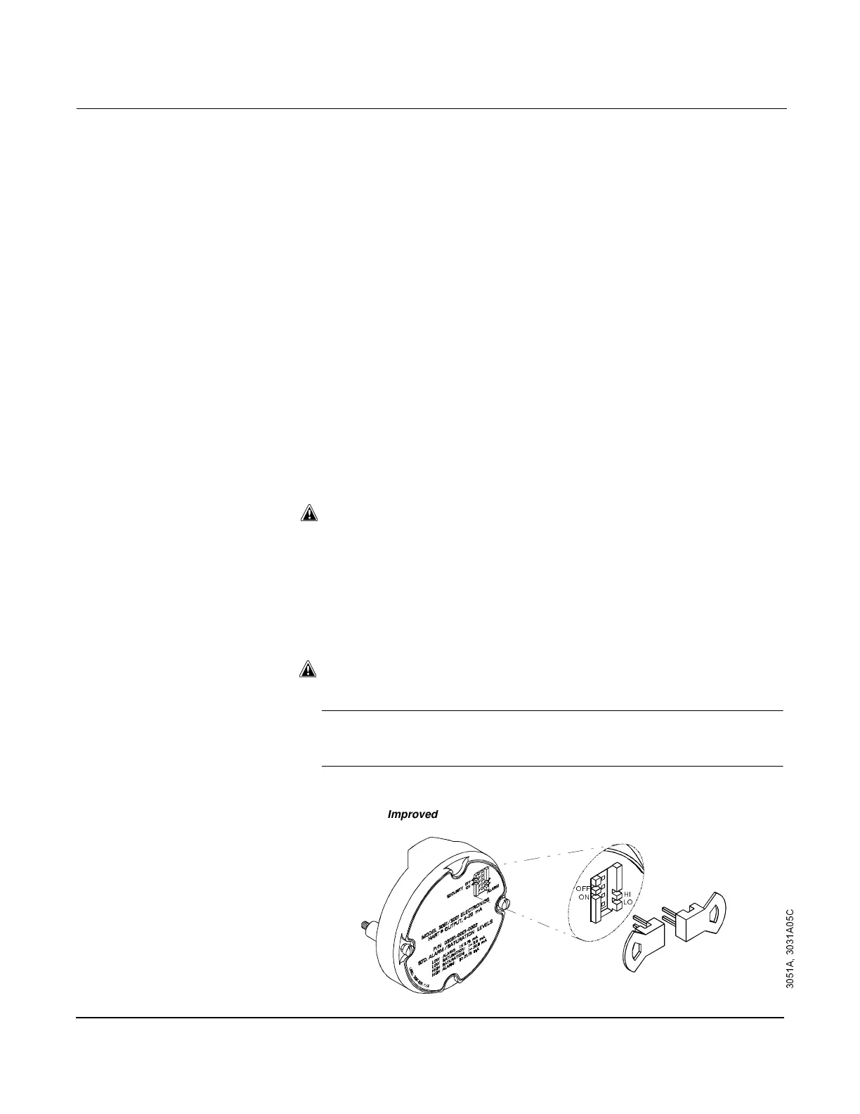
Flowmeter Security You can prevent changes to the flowmeter configuration data with the
write protection jumper. Position the jumper on the flowmeter circuit
board in the “ON” position to prevent accidental or deliberate change of
configuration data. Figure 5-1 shows the jumper positions for 4–20 mA
flowmeters. For flowmeters with an optional LCD meter, see “LCD
Meter” in Installation Options.
If the flowmeter write protection jumper is in the “ON” position, the
flowmeter will not accept any “writes” to its memory. Configuration
changes (such as digital trim and reranging) cannot take place when
the flowmeter security is on. To reposition the jumper, perform the
following procedure.
1. If the flowmeter is installed, secure the loop, and remove power.
2. Remove the housing cover opposite the field terminal side. Do not
remove the flowmeter covers in explosive atmospheres when the
circuit is alive.
3. Reposition the jumper. See Figure 5-1 for the ON and OFF jumper
positions. Previous circuit boards carried a two-pin or three-pin
jumper assembly on the connector side of the board (see Figure
5-1). To activate security using a two-pin version, install the
jumper. To activate security with the three-pin assembly, move the
jumper to the ON pin position.
4. Reattach the flowmeter cover. Flowmeter covers must be fully
engaged to meet explosion-proof requirements.
NOTE
If the security jumper is not installed, the flowmeter will continue to
operate in the security OFF configuration.
Figure 5-1. 4–20 mA Flowmeter
Electronics Boards
Alarm
Security
/2
+,
2))
21
mprove
ectron
cs
oar
$
$
&

 Loading...