3-7
Install Electrical Grounds Install field wiring ground (optional), and ground the electronics
case (required).
Field Wiring Ground
1. Field wiring may be grounded at any one point on the signal loop,
or it may be left ungrounded. The negative terminal of the power
supply is a recommended grounding point.
Ground the Electronics Case
2. The electronics case should always be grounded in accordance with
national and local electrical codes. The most effective electronics
case grounding method is a direct connection to the earth ground
with minimal impedance. Methods for grounding the electronics
case include:
Internal Ground Connection: Inside the FIELD TERMINALS
side of the electronics housing is the Internal Ground Connection
screw. This screw is identified by a ground symbol: .
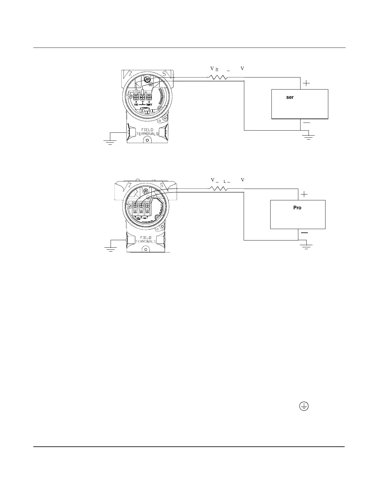
Figure 3-4.
Field Wiring Connections.
1100
9
> R
L
> 250
9
User-Provided
Power Supply
Signal loop may be grounded at
any point or left ungrounded
(see step 7.b)
1100
9
> R
L
> 250
9
User-Provided
Power Supply
Signal loop may be grounded at
any point or left ungrounded
(see step 7.b)
PREVIOUS TERMINAL BLOCK
IMPROVED TERMINAL BLOCK

 Loading...