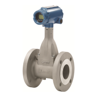
Rosemount Model 1195/ProPlate/Mass ProPlate
5-2
Commissioning the
Flowmeter on the Bench
Commissioning consists of testing the flowmeter, testing the loop, and
verifying flowmeter configuration data. You may commission ProPlate
flowmeters either before or after installation. Commissioning the
flowmeter on the bench before installation ensures that all flowmeter
components are in good working order and acquaints you with the
operation of the device.
To avoid exposing the flowmeter electronics to the plant environment
after installation, set the failure mode and flowmeter security jumpers
during the commissioning stage on the bench.
Failure Mode Alarm As part of normal operation, the ProPlate continuously monitors its
own operation. This automatic diagnostic routine is a timed series of
checks repeated continuously. If the diagnostic routine detects a failure,
the flowmeter drives its output either below or above specific values
depending on the position of the failure mode jumper.
• For 4–20 mA flowmeters factory-configured for standard
operation, the flowmeter drives its output either below 3.75 mA
or above 21.75 mA.
• For 4–20 mA flowmeters factory-configured for
NAMUR-compliant operation, the flowmeter drives its output
either below 3.6 mA or above 22.5 mA.
The failure mode alarm jumper is located on the front of the electronics
board inside of the electronics housing cover. The position of this
jumper determines whether the output is driven high or low when a
failure is detected (see Figure Figure 5-1 on page 5-4). If the alarm
jumper is not installed the flowmeter will operate normally, and the
default alarm condition will be high.
NOTE
The failure mode alarm jumper pins occupy one row of a ten-pin socket
that also is used to attach the optional LCD meter. In order to function
appropriately, the jumper must be positioned correctly, as shown in
Figure 5-1 on page 5-4.
Failure Mode Alarm vs. Saturation Output Values
The failure mode alarm output levels differ from the output values that
occur when applied pressure is outside the range points. When pressure
is outside the range points, the analog output continues to track the
input pressure until reaching the saturation value listed below; the
output does not exceed the listed saturation value regardless of the
applied pressure. For example, with standard alarm and saturation
levels and pressures outside the 4–20 range points, the output
saturates at 3.9 mA or 20.8 mA. When the flowmeter diagnostics detect
a failure, the analog output is set to a specific alarm value that differs
from the saturation value to allow for proper troubleshooting.
Table 5-1. Analog Output: Standard
Alarm Values vs. Saturation Values.
Level 4–20 mA Saturation Value 4–20 mA Alarm Value
Low 3.9 mA
3.75 mA

 Loading...


