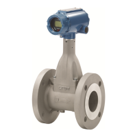
Rosemount Model 1195/ProPlate/Mass ProPlate
2-4
The transmitter cannot be mounted directly on the orifice body when a
seal liquid is used. Pressure lines and the optional pressure connectors
are required in this case. Figure 2-3 illustrates some typical
installations of remote connection adapters.
Transmitter Orientation The high pressure port on the upstream side of the orifice assembly must
be connected to the high pressure side of the differential transmitter.
Position the transmitter drain and vent plugs so that trapped
gases can be periodically vented and condensate can be drained.
Before tightening the assembly bolts, make sure that the side of the
orifice plate labeled “INLET” faces upstream.
Tighten the two body bolts to a torque of 60 ft.-lb. Tighten the four
transmitter, manifold, or connection adaptor bolts to a torque
of 38 ft.-lb.
PROPLATE/
MASS PROPLATE
FLOWMETER
This section describes the orientation and location for installing the
ProPlate flowmeter. Read it thoroughly before any installation is
performed.
Safety Messages Instructions and procedures in this section may require special
precautions to ensure the safety of the personnel performing the
operations. Please refer to the following safety messages before
performing any operation in this section.
Exceeding the pressure or temperature ratings of the orifice assembly or the transmitter
can cause severe personal injury or equipment damage. Follow the pressure and
temperature limits specifications in Section 10: Specifications and Reference Data.
Loose bolts and fitting sags can cause leakage. Ensure all bolts and fittings on the
orifice assembly, such as transmitter body, pressure connector, drain, vent are tight
before applying pressure to the process piping and orifice/transmitter assembly.
Explosions could result in death or serious injury:
• Do not remove the transmitter cover in explosive atmospheres when the circuit
is alive.
• Before connecting a HART-based communicator in an explosive atmosphere,
make sure the instruments in the loop are installed in accordance with
intrinsically safe or non-incendive field wiring practices.
• Verify that the operating atmosphere of the transmitter is consistent with the
appropriate hazardous locations certifications.
• Both transmitter covers must be fully engaged to meet explosion-proof
requirements.

 Loading...


