4
FUNCTIONS
4.7 Output (Y) Status Setting for Switching STOP to RUN
4 - 58
1
OVERVIEW
2
SYSTEM
CONFIGURATION
3
SPECIFICATIONS
4
FUNCTIONS
5
SETTING AND
PROCEDURES
6
I/O NUMBER
ASSIGNMENT
7
MEMORIES AND
FILES
8
INSTALLING /
UNINSTALLING
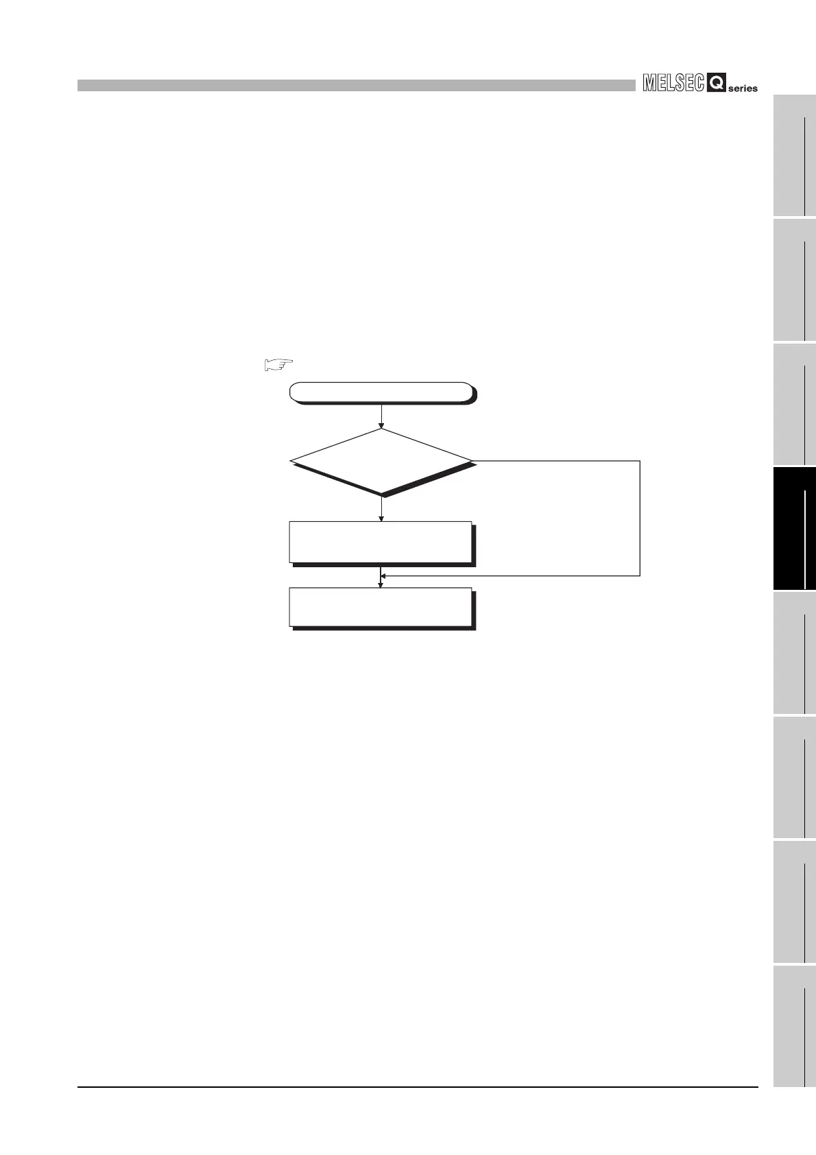
(3) Processing
(a) Previous state (Default)
The outputs status (Y) immediately before the module is changed into the STOP
status is output.
Then, output from the user program is enabled.
(b) Recalculate
The outputs turn to OFF.
Then, output from the user program is enabled.
For the case where the output (Y) is forcibly turned ON in the STOP status, refer
to the following.
(5)
Figure 4.44 Output (Y) processing when STOP status is changed to RUN status
STOP status to RUN status
Previous state?
NO (Recalculate)
YES (Previous state (Default))
The outputs (Y) status immediately
before the module is changed into
the STOP status is output.
Output (Y) from the user
program is enabled.