5 - 20
5.4 Parts Names and Functions
5
SETTINGS AND PROCEDURES BEFORE OPERATION
(1) LED indicator specifications
(a) In normal operation mode (When the MODE LED is lit "green")
Change the operation mode by the switch.(
This section (2), (3))
* 1 All LEDs turn off while the module is reset.
* 2 When a system watchdog timer error has occurred, the RUN LED and MODE LED turn off and
the ERR. LED flashes.
* 3 Refer to Chapter 10 for details of the bus interface function.
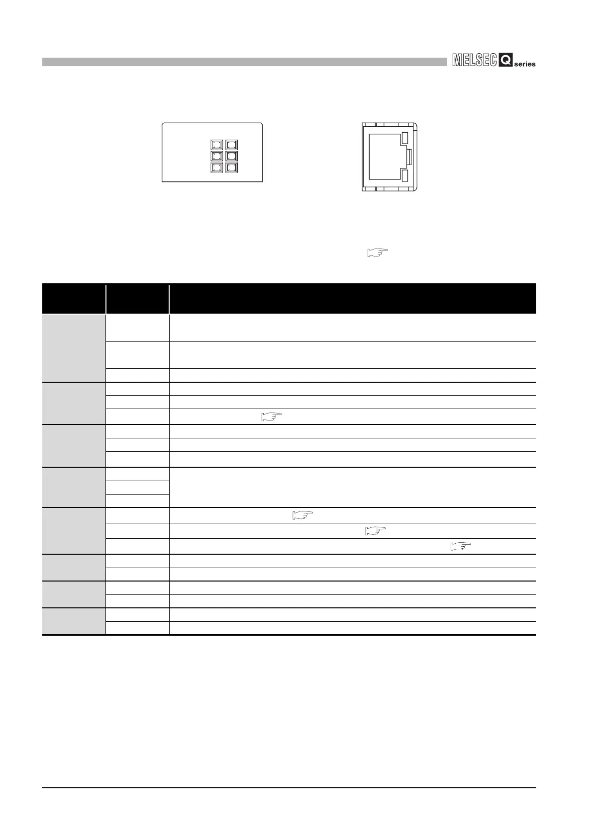
Figure 5.20 LED indicators
Table5.3 LED indicators and statuses in normal operation mode
LED
indicator
*1
LED status Description
RUN
On
The C Controller module is in the RUN status.
(Output (Y) from user program and writing to buffer memory are enabled)
Off
The C Controller module is in the STOP/PAUSE status.
(Output (Y) from user program and writing to buffer memory are disabled)
Flashing The script file "STARTUP.CMD" is in execution.
MODE
On Normal operation mode (VxWorks running)
Off Hardware fault occurred or during reset
Flashing
Shutdown completed ( Section 5.7.4 (2))
ERR.
On Continue error occurred
Off Normal
Flashing
Stop error occurred
*2
USER
On
Can be controlled by the user program QBF_ControlLED function
*3
Off
Flashing
CF CARD
On
CompactFlash card mounted ( Section 5.8.2)
Off
CompactFlash card not mounted or unmounted ( Section 5.8.2)
Flashing
CompactFlash card being unmounted by the RESET/SELECT switch (
Section 5.8.3)
CH2 SD/RD
On CH2 side (RS-232 interface) sending or receiving data
Off Data not transmitted
100M
On Being connected at 100Mbps
Off Being connected at 10Mbps
SD/RD
On/Flashing CH1 side (10BASE-T/100BASE-TX interface) sending or receiving data
Off Data not transmitted
100
M
SD/
RD
100BASE-TX
CH1 10BASE-T/
MODE
ERR.
USER
RUN
CF CARD
CH2 SD/RD
-V-H01
Q06CCPU