5
SETTINGS AND PROCEDURES BEFORE OPERATION
5.4 Parts Names and Functions
5 - 21
1
OVERVIEW
2
SYSTEM
CONFIGURATION
3
SPECIFICATIONS
4
FUNCTIONS
5
SETTING AND
PROCEDURES
6
I/O NUMBER
ASSIGNMENT
7
MEMORIES AND
FILES
8
INSTALLING /
UNINSTALLING
(b) In hardware self-diagnostic operation mode (When the MODE LED is lit
"orange")
Change the operation mode by the switch.(
This section (2), (3))
Remark
Refer to Section 18.5 for the hardware self-diagnostics function.
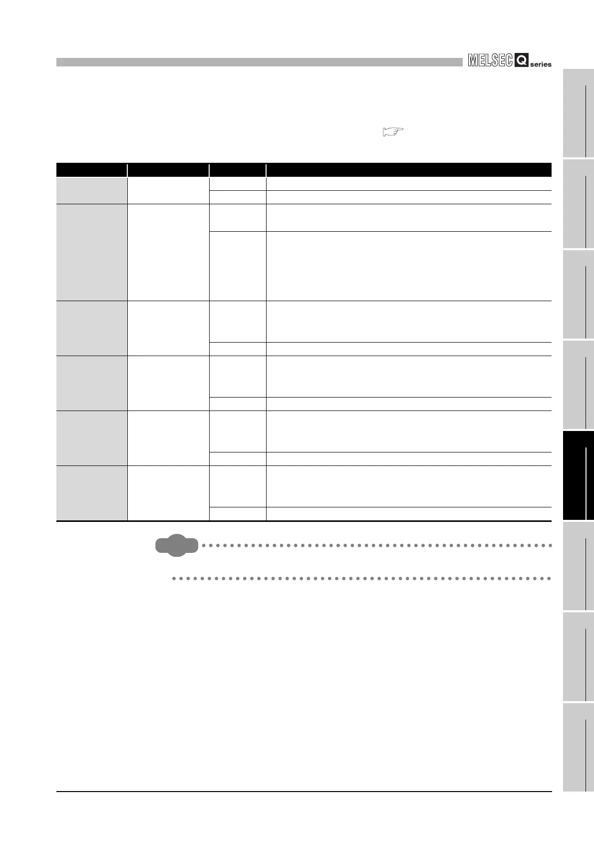
Table5.4 LED indicators and statuses in hardware self-diagnostic operation mode
LED indicator Name LED status Description
MODE MODE
On Hardware self-diagnostic mode
Off Hardware fault occurred or the module is being reset
ERR.
Hardware self-
diagnostic error
Off
When all LEDs but the MODE LED turn off, it indicates that the self-
diagnostic test has not been executed yet or is normally completed.
Flashing
An error has occurred when the mode (Mode 1, Mode 2, Mode 3,
Default setting mode) selected by SELECT operation was executed.
The error location can be confirmed by the ON/OFF status of the
following LEDs.
"RUN" "CF CARD" "CH2 SD/RD" "USER"
RUN
Mode 1/
Error location
indication
On
ERR. LED off : Mode 1 selected
ERR. LED flashing : Indicates the location of the error that occurred by
execution of Mode 1 to 3.
Flashing Mode 1 in execution
CF CARD
Mode 2/
Error location
indication
On
ERR. LED off : Mode 2 selected
ERR. LED flashing : Indicates the location of the error that occurred by
execution of Mode 1 to 3.
Flashing Mode 2 in execution
CH2 SD/RD
Mode 3/
Error location
indication
On
ERR. LED off : Mode 3 selected
ERR. LED flashing : Indicates the location of the error that occurred by
execution of Mode 1 to 3.
Flashing Mode 3 in execution
USER
Default setting
mode/
Error location
indication
On
ERR. LED off : Default setting mode selected
ERR. LED flashing : Error occurred during execution of Default setting
mode
Flashing Default setting mode in execution

 Loading...


