6 - 15
6.5 I/O Number Assignment
6.5.1 I/O number of base unit
6
I/O NUMBER ASSIGNMENT
To assign I/O numbers, follow the items below:
(1) Number of slots of base units
The number of slots of base units is set in Base mode.( Section 6.3)
(a) In Auto mode
The number of slots is determined as the available number of modules mounted
to each base unit.
5 slots are assigned to a 5-slot base unit, and 12 slots are assigned to a 12-slot
base unit.
(b) In Detail mode
The number of slots set on the <<I/O assignment setting>> tab of the C Controller
setting utility is used.
(2) Order of I/O number assignment
The I/O numbers are assigned to the modules from left to right consecutively, starting
from 0
H assigned to the module on the right of the C Controller module in the main
base unit.
(3) Order of I/O number assignment for extension base units
The I/O numbers next to the last number of the I/O number of the main base unit are
assigned to extension base units.
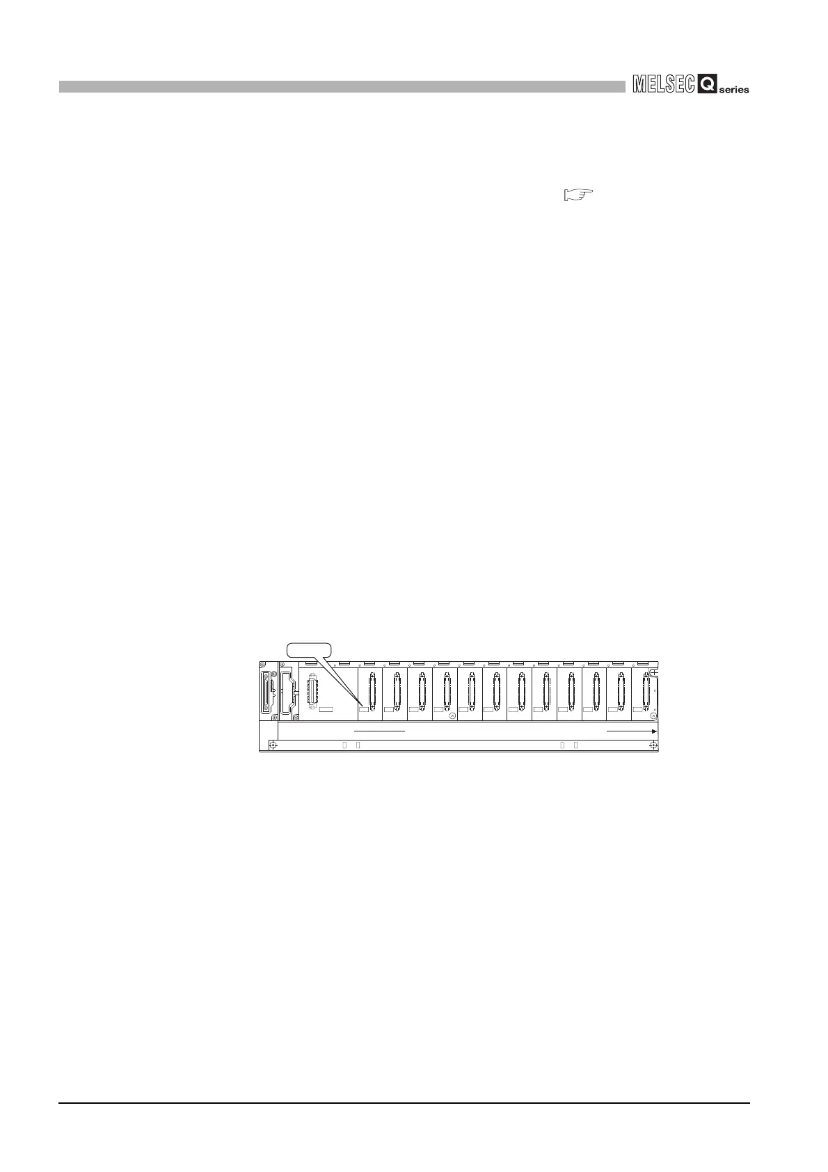
The I/O numbers are assigned to the extension base units from left (I/O 0) to right
consecutively as shown in Figure 6.15, in the order in which the setting connectors of
the extension base unit are set.
(4) I/O numbers of each slot
Each slot of base units occupies the points of I/O numbers of the mounted I/O
modules or intelligent function modules .
When a 32-point input module is mounted on the right of C Controller module, X0 to
X1F are assigned as I/O numbers.
Figure 6.15 I/O number assignment order
I/O11I/O10I/O9I/O8I/O7I/O6I/O5I/O4I/O3I/O2I/O1I/O0
POWER
5V
56
OUTIN
I/O 0
Serial numbers inorder from left to right

 Loading...


