9 - 30
9.2 C Controller Setting Utility
9.2.5 Operating Module monitor screen
9
UTILITY OPERATION
* 4 Refer to the following for the buffer memory address of the intelligent function module.
Manual of corresponding module
* 5 Refer to the following for the CPU shared memory addresses.
Section 14.3.1
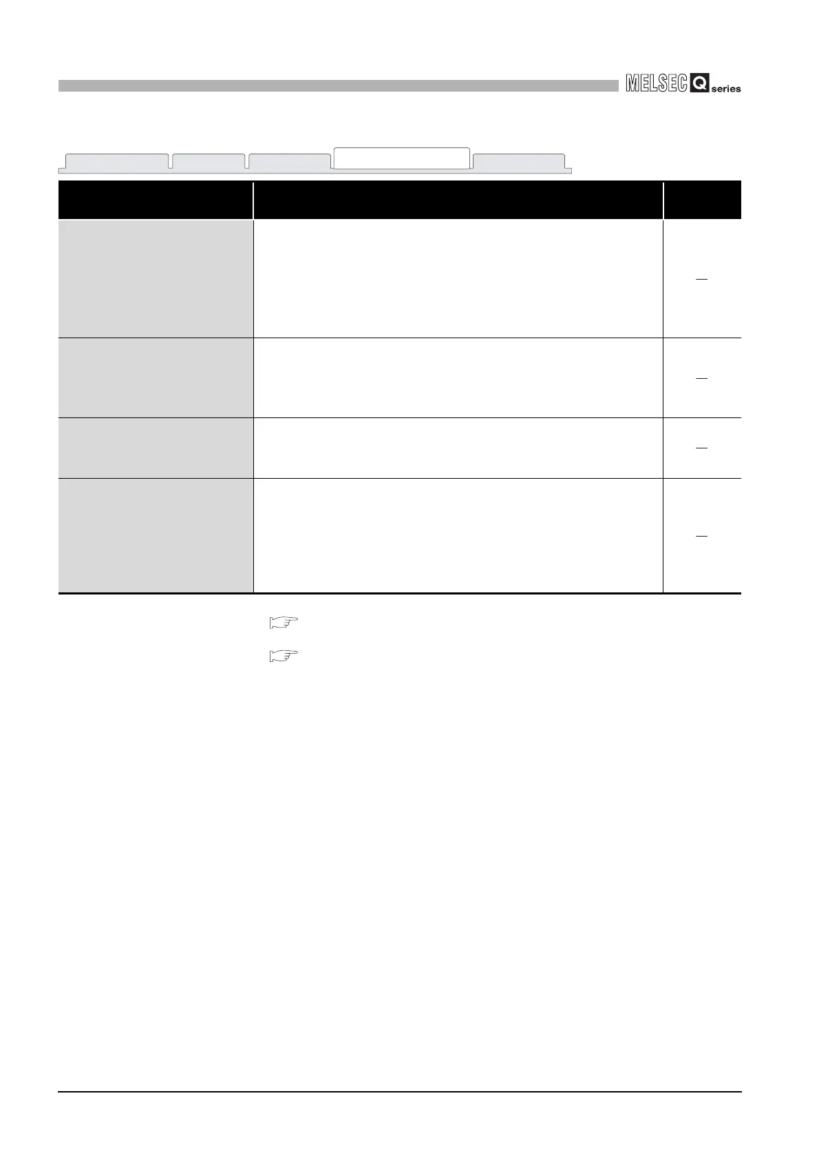
Table9.13 Explanation of Module monitor screen (Continued)
Item Description
Reference
section
Buffer memory offset
Specify the buffer memory offset address of the intelligent function
module to be monitored.
*4
This address can only be set for the intelligent function module.
This area display is switched to "CPU common memory offset" when the
slot to which a CPU module is installed is specified in "Slot No."
(Initial value: 0, Setting range: 0 or more)
CPU common memory
Specify the address of the CPU shared memory to be monitored.
*5
This area display is switched to "Buffer memory offset" when the slot to
which any other than CPU modules is installed is specified in "Slot No."
(Initial value: 0, Setting range: 0 to FFF
H)
3) Buffer memory area
Displays the buffer memory status of the slot specified in the slot No.
Double-clicking this displays the "Data Change" screen. Entering a value
on the "Data Change" screen executes forced write.
*3
Format
Select the format ("DEC.", "HEX.") of displaying the input (X) and output
(Y) status in words and the buffer memory status.
The selected format is also reflected on the numerical input format used
for the forced word output of the output (Y) status or the forced write to the
buffer memory.
(Initial value: "HEX.", Setting range: "DEC." or "HEX.")
Module information Event history SRAM monitor
Module monitor
Online operation

 Loading...


