9
UTILITY OPERATION
9.2 C Controller Setting Utility
9.2.5 Operating Module monitor screen
9 - 29
9
UTILITY OPERATION
10
FUNCTIONS AND
PROGRAMMING
11
OVERVIEW OF
MULTIPLE CPU
SYSTEM
12
MULTIPLE CPU
SYSTEM
CONFIGURATION
13
MULTIPLE CPU
SYSTEM
CONCEPT
14
COMMUNICATIONS
BETWEEN CPU
MODULES
15
PARAMETERS
ADDED FOR
MULTIPLE CPU
16
PRECAUTIONS FOR
USE OF AnS SERIES
MODULE
* 2 The input and output data display covers the number of points assigned in the parameter setting
(I/O assignment setting) of the module installed to the specified slot No.
* 3 The input format of the numerical value for forced output or forced write is the same as selected in
"Format".
(To next page)
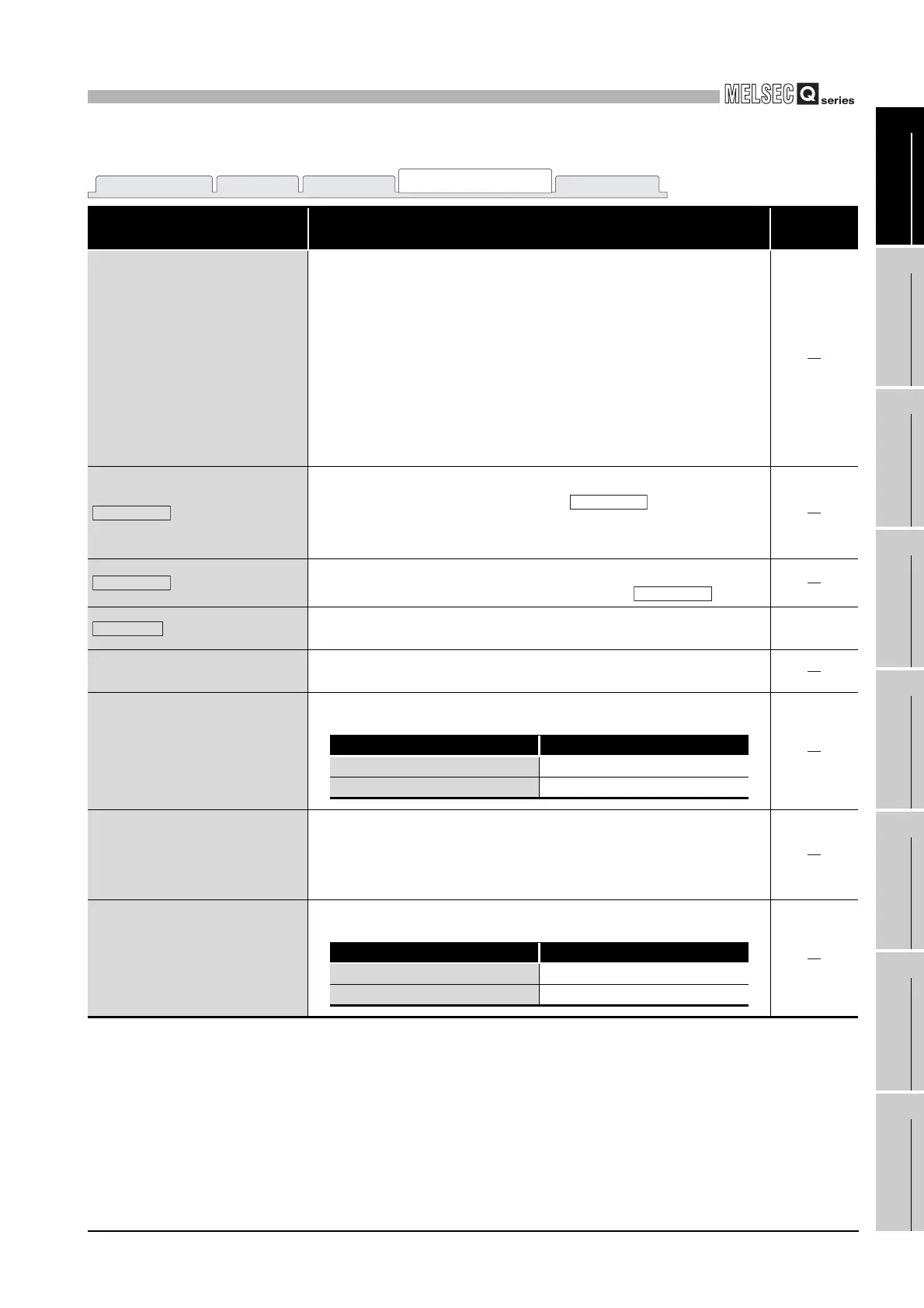
Table9.13 Explanation of Module monitor screen (Continued)
Item Description
Reference
section
Type
Displays the number of I/O points and type of the module if the slot where
any other than CPU modules is installed is specified in "Slot No."
The value within parentheses is the "points" value in the parameter setting
(I/O assignment setting).
Displays CPU No. and "own station" when the slot where a CPU module
(host) is installed is specified in "Slot No."
Displays CPU No. when the slot where a CPU module (another) is
installed is specified in "Slot No."
Displays "CPU (Empty)" when the slot to which "CPU (Empty)" is set in I/
O assignment is specified in "Slot No."
button
Starts monitoring.
During monitoring, this button changes to , and "*" flashes at
top right of the button.
In an offline status, this button cannot be clicked.
button
Stops monitoring.
When monitoring is stopped, this button changes to .
button
Displays the system information screen.
During monitoring, this button cannot be clicked.
This section
(3)
Input
*2
Displays the input (X) status of the slot specified by the slot No. in word
units.
1) X area
*2
Displays the input (X) status of the slot specified by the slot No. in bit
units.
Display Description
0OFF
1ON
Output
*2
Displays the output (Y) status of the slot specified by the slot No. in word
units.
Double-clicking this displays the "Data Change" screen.
Entering a value into the "Data Change" screen performs forced output.
*3
2) Y area
*2
Displays the output (Y) status of the slot specified by the slot No. in bit
units. Double-clicking this performs forced output.
Display Description
0OFF
1ON
Module information Event history SRAM monitor
Module monitor
Online operation
Start monitor
Stop monitor
Stop monitor
Start monitor
Information

 Loading...


