13
MULTIPLE CPU SYSTEM CONCEPT
13.2 CPU No. of CPU Module
13 - 10
9
UTILITY OPERATION
10
FUNCTIONS AND
PROGRAMMING
11
OVERVIEW OF
MULTIPLE CPU
SYSTEM
12
MULTIPLE CPU
SYSTEM
CONFIGURATION
13
MULTIPLE CPU
SYSTEM
CONCEPT
14
COMMUNICATIONS
BETWEEN CPU
MODULES
15
PARAMETERS
ADDED FOR
MULTIPLE CPU
16
PRECAUTIONS FOR
USE OF AnS SERIES
MODULE
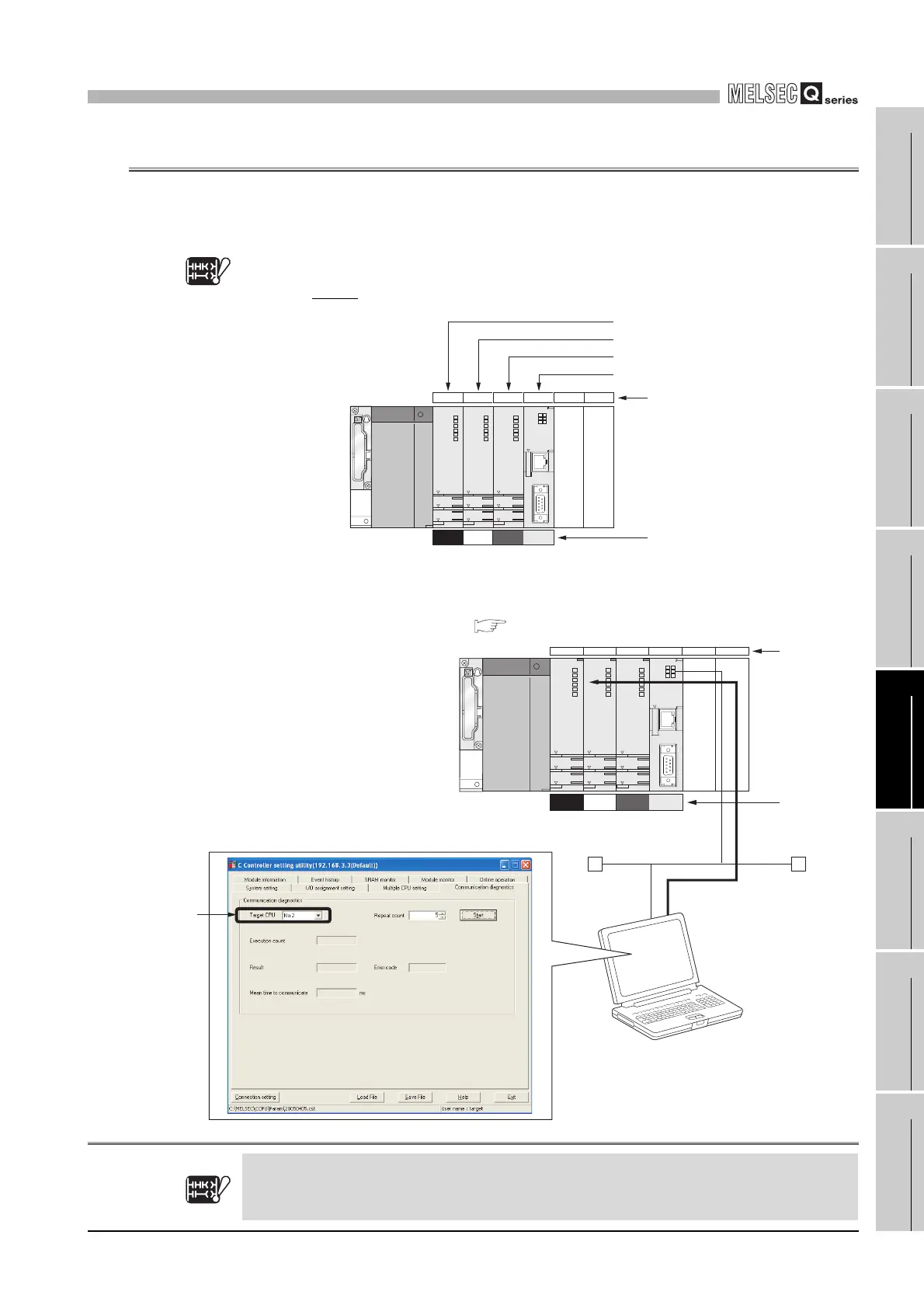
13.2 CPU No. of CPU Module
(1) CPU No. allocation
CPU numbers are allocated for identifying the CPU modules mounted on the main
base unit in the multiple CPU system. CPU No.1 is allocated to the CPU slot, and
CPU No.2, No.3 and No.4 are allocated to the right of the CPU No.1 in this
order.
Note13.1
íç1
The CPU No. is used for the following applications.
• Communication diagnostics on the <<Communication diagnostics>> tab of the C
Controller setting utility. ( Section 9.2.10)
Figure 13.12 CPU No. allocation
íç1
Figure 13.13 Connection target setting on C Controller setting utility
Basic
Note13.1
CPU
012 34
CPU slot : CPU No.1
slot 0 : CPU No.2
slot 1 : CPU No.3
slot 2 : CPU No.4
Slot number
CPU number
4
2
When the Basic model QCPU is used, there is no CPU No. 4 since up to 3 CPU modules can be
mounted.
Note13.1
Basic
Slot number
34CPU 0 1 2
Communicate
with CPU No. 2.
CPU numbe
4
2
Ethernet
Specify
CPU No. 2
Developer envirament
(personal computer)

 Loading...


