3. Secure the individual wires using the 3.5 mm screwdriver.
Note
The grounding conductor EB must have a cross-section of at least 4 mm
2
. Connect the other
end of the grounding conductor EB with the ground bus EB.
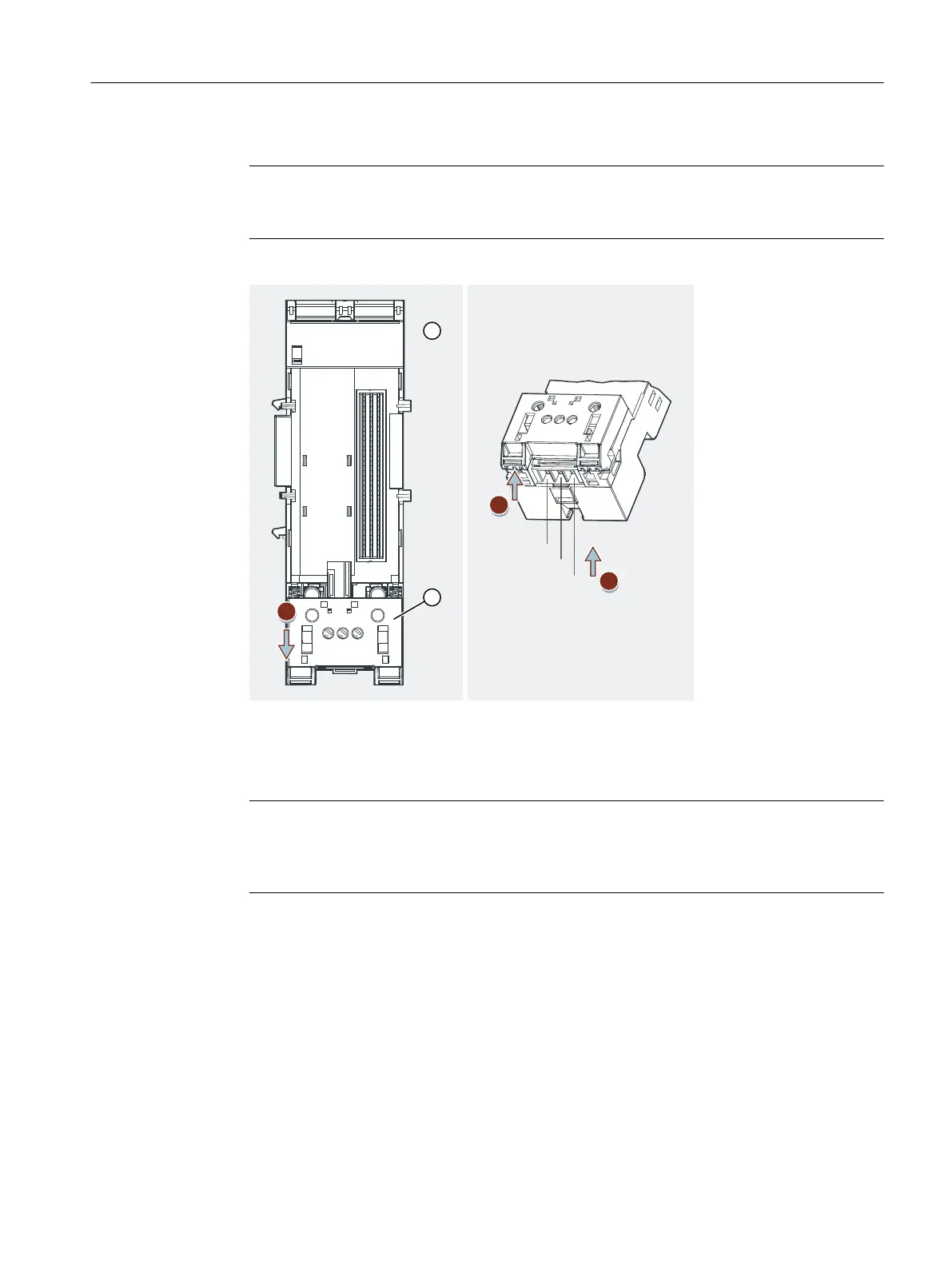
4. Lift up the slide at the front until it moves up by itself.
① Terminal module TM‑PS‑A
② Catch
Figure 6-5 Connect supply voltage and grounding conductor EB to the TM‑PS‑A
Note
When wiring the TM‑PS‑A (6ES7193-7DA20-0AA0) or TM‑PS‑B (6ES7193-7DB20-0AA0),
make sure that you connect phase L1 and neutral N correctly. Only then is trouble-free
operation of the ET 200iSP guaranteed.
6.4.6 Wiring Terminal Modules TM-IM/EM and TM-IM/IM
Properties
At the terminal module TM-IM/EM, connect the bus connector for the PROFIBUS RS 485-IS. The
connector is on the left-hand side of the module. The terminal module TM-IM/EM is also the
interface to the actuators and sensors. The connectors are on the right-hand side of the module.
Wiring
6.4 Wiring the ET 200iSP
ET 200iSP
Operating Instructions, 11/2022, A5E00247483-AK 131

 Loading...


