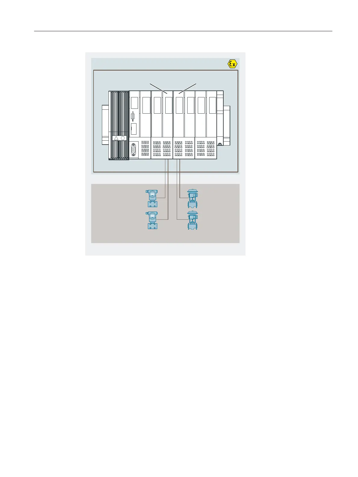
+D]DUGRXVDUHD
(7L63LQWKHHQFORVXUH
HJ
WUDQVPLWWHUVDFWXDWRUV
ORZHVWOHYHO
,QWHOOLJHQWILHOG
GHYLFHVHJ
+$57GHYLFH
$,,:,5(+$57 +$570DVWHU $2,+$57
6,3$5736
6,75$163
Figure 14-9 Location of the HART analog modules in the distributed system
14.10.5 Using HART
System environment for using HART
To operate an intelligent eld device with HART functionality, you require the following system
environment:
Current loop 4 - 20 mA via the analog electronic modules: 4 AI I 2WIRE HART, 4 AI I 4WIRE HART
or 4 AO I HART.
The HART analog module takes over the function of a "master" by receiving the commands from
the HART parameter assignment tool, passing them on to the smart eld device and then
returning the reply messages. The interface of the HART analog module is represented by data
records that are transferred via the I/O bus. These data records are generated or interpreted by
the HART parameter assignment tool (SIMATIC PDM).
The analog values in 16-bit format and up to 4 IEEE variables (primary or non-primary variable)
are entered in the process image of the inputs and outputs.
Analog electronic modules
14.10 Basics of HART
ET 200iSP
Operating Instructions, 11/2022, A5E00247483-AK 393

 Loading...


