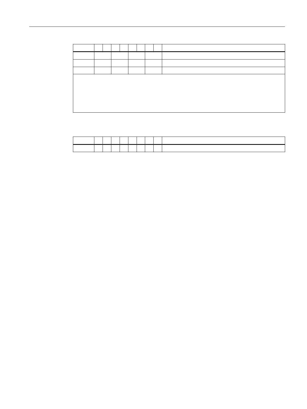
Byte 7 6 5 4 3 2 1 0 Description
Byte 22 28 27 26 25 Slot 25 to 28
Byte 23 32 31 30 29 Slot 29 to 32
Byte 24 35 34 33 Slot 33 to 35
Legend for the entry of the module status on slot x:
• 00
B
: Module OK; valid data
• 01
B
: Module error; invalid data
• 10
B
: incorrect module; invalid data
• 11
B
: no module (or failure of the module); invalid data
Table 7-35 Example: Slot 35
Byte 7 6 5 4 3 2 1 0 Description
Byte 24 1 0 10
B
: incorrect module; invalid data
7.13.11 Channel-related diagnostics with PROFIBUS
Denition
Channel-related diagnostics provides information on channel faults of modules and provides
more detail than ID-related diagnostics.
For each channel-related diagnostics, 3 bytes are inserted according to the IEC 61784‑1:2002
Ed1 CP 3/1 standard.
The channel-related diagnostic information follows the module status.
Channel-related diagnostics does not aect the module status.
Important: The group diagnostics must be switched on for each module!
Commissioning and Diagnostics
7.13 Diagnostics with STEP 7 with PROFIBUS
ET 200iSP
Operating Instructions, 11/2022, A5E00247483-AK 207

 Loading...


