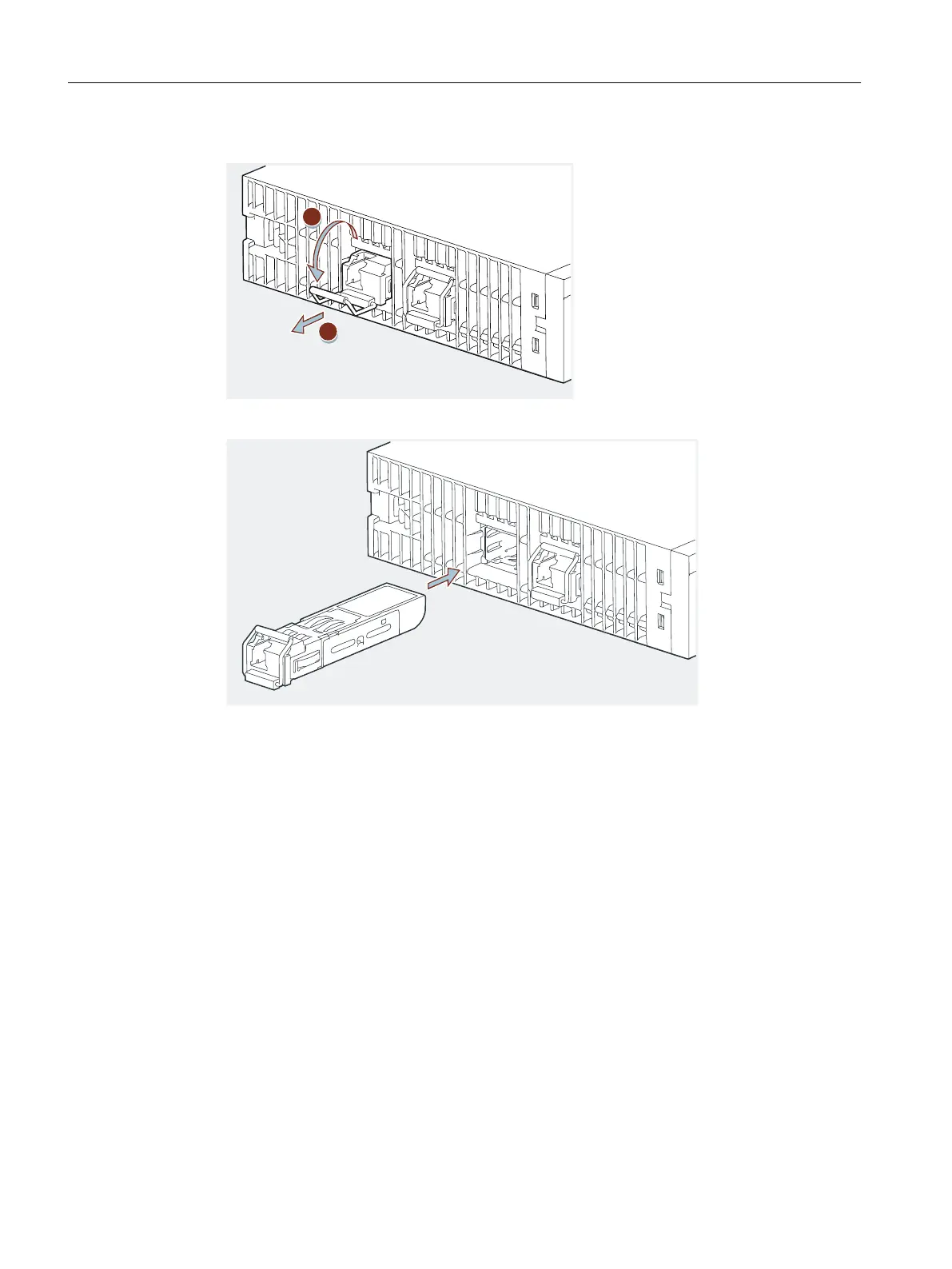
4. Pull the (old) optical transceiver out of the IM 152-1PN.
5. Insert the (new) optical transceiver into the IM 152-1PN until the transceiver snaps into place.
6. Insert the end of the ber-optic cable into the optical transceiver until the cable snaps into
place.
7. Check that the LEDs "LK 1" and "LK 2" of the IM 152-1PN are lit green.
Both LEDs must be green to prevent loss of the data connection during operation.
6.5.6 Plugging and pulling the ber-optic cable into the transceiver
Cable pulling
Observe the following points when pulling ber-optic cables:
• Note the permissible pull forces for the respective ber-optic cable in the associated data
sheet and adhere to them.
• Avoid laying cable out (longer unwinding) before pulling in the cable.
• If possible, lay the ber-optic cable directly from the cable reel.
• Do not unwind the ber-optic cable laterally over the reel ange (risk of twisting).
• If possible, use a cable pull sock when pulling in the ber-optic cable.
Wiring
6.5 Inserting and labeling the power supply, interface module, and electronic modules
ET 200iSP
152 Operating Instructions, 11/2022, A5E00247483-AK

 Loading...


