Format of the analog values S7
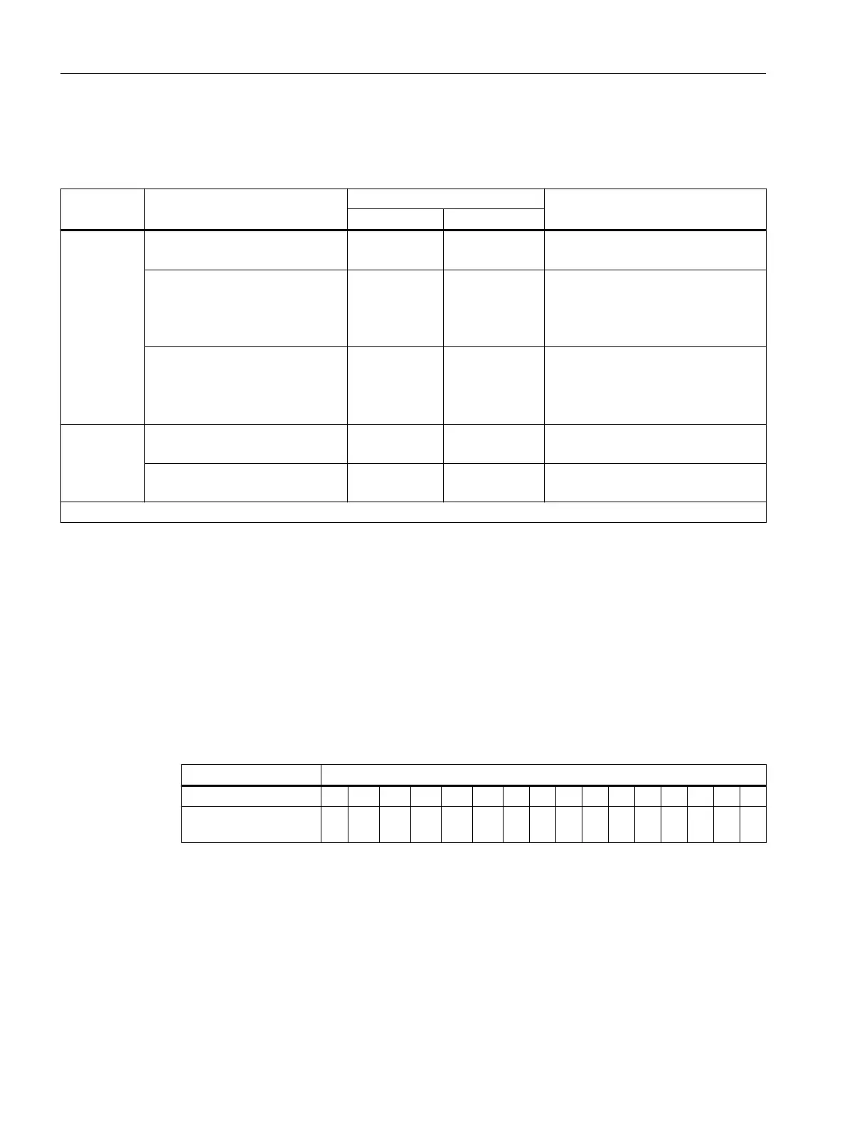
Table 14-8 Measured values in the event of a wire break depending on diagnostic enables (format S7)
Module Parameter assignment Measured values Explanation
decimal hexadecimal
4 AI I
• "Wire break" diagnostics ena‐
bled
32767 7FFF
H
• Diagnostic message "Wire break"
• "Wire break" diagnostics disa‐
bled
1
• Enable "Overow/Underow"
diagnostics
-32768 8000
H
• Measured value after exiting the
underrange
• Diagnostic message " Low limit ex‐
ceeded"
• "Wire break" diagnostics disa‐
bled
1
• "Overow/underow" diagnos‐
tics disabled
- -
• Measured value after exiting the
underrange
4 AI RTD
4 AI TC
• "Wire break" diagnostics ena‐
bled
32767 7FFF
H
• Diagnostic message "Wire break"
• "Wire break" diagnostics disa‐
bled
-
-
• Open input: Undened measured
value
1
Measuring range limits for the detection of wire breaks in the measuring range 4 to 20 mA: at < 3.6 mA
14.8.2 Analog value representation for measuring ranges with SIMATIC S7
Analog value representation
The digitized analog value is the same for input and output values with the same nominal range.
Analog values are represented in two's complement.
The following table shows the analog value representation of the analog electronic modules.
Table 14-9 Analog value representation (SIMATIC S7)
Resolution Analog value
Bit number 15 14 13 12 11 10 9 8 7 6 5 4 3 2 1 0
Pulse value of the bits Sig
n
2
14
2
13
2
12
2
11
2
10
2
9
2
8
2
7
2
6
2
5
2
4
2
3
2
2
2
1
2
0
Sign
The sign of the analog value is always in bit number 15:
• "0" → +
• "1" → -
Analog electronic modules
14.8 Representation of analog values
ET 200iSP
376 Operating Instructions, 11/2022, A5E00247483-AK

 Loading...


