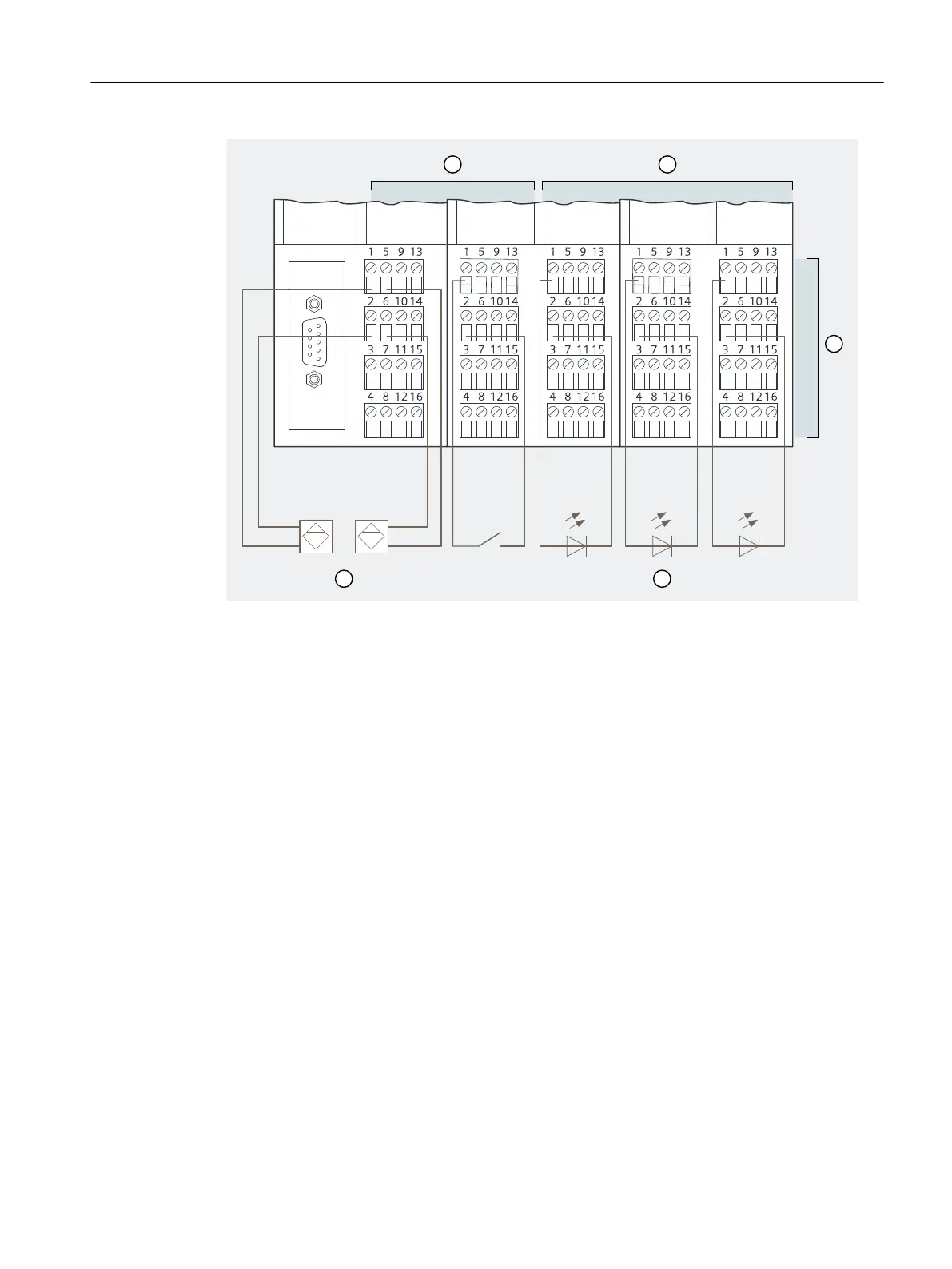
① 2 x 8 DI NAMUR
② 3 x 4 DO DC17.4/27mA
③ Terminals
④ LEDs
⑤ NAMUR sensor
Figure 3-6 Wiring of the ET 200iSP modules
3.8 Inserting the interface module and the electronics modules
Inserting Modules
Insert the modules in the following order:
• Power Supply PS DC24V
• Interface module
• 2 x 8 DI NAMUR
• 3 x 4 DO DC17.4V/27mA
See also
Installing Terminal Modules for the Interface Module and Electronics Modules (Page 112)
Commissioning guideline
3.8 Inserting the interface module and the electronics modules
ET 200iSP
Operating Instructions, 11/2022, A5E00247483-AK 47

 Loading...


