13.5.2 Digital electronic module 4 DO
Parameters 4 DO
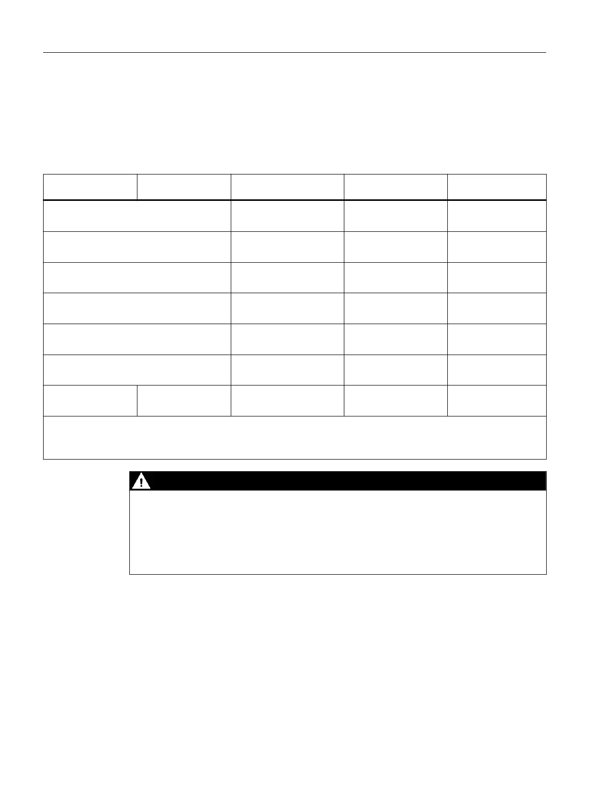
Table 13-18 Parameters for 4 DO
Parameters: shut
down "H" modules
Parameters: shut
down "L" modules
Range of values Default Applicability
Parallel connection of channels
1
• Yes
• No
No Channel 0
Channel 2
Response to CPU/ master STOP
• Use substitute value
• Keep last value
Use substitute value Channel
Substitute value
• 0
• 1
0 Channel
Group diagnostics
• Enabled
• Disabled
Enabled Channel
Diagnostics, Wire break
2
• Enabled
• Disabled
Enabled Channel
Diagnostics: wire break
• Enabled
• Disabled
Enabled Channel
--- Disable shutdown sig‐
nal
3
• Enabled
• Disabled
Disabled Module
1
Not possible with 4 DO DC23.1V/20mA.
2
The wire break is detected in the digital output module only with "1" signal.
3
Only possible with SIMATIC PDM and in HW Cong with "*" after the article number.
DANGER
Substitute values in Flash memory
The substitute values are stored in the ash memory of the interface module. These are output
at the next startup of the ET 200iSP until the ET 200iSP exchanges data with the DP master.
Note this behavior when changing the ET 200iSP to another conguration environment.
Remedy: Delete the ash memory of the interface module beforehand.
Digital electronic modules
13.5 Parameters of the digital electronic modules
ET 200iSP
338 Operating Instructions, 11/2022, A5E00247483-AK

 Loading...


