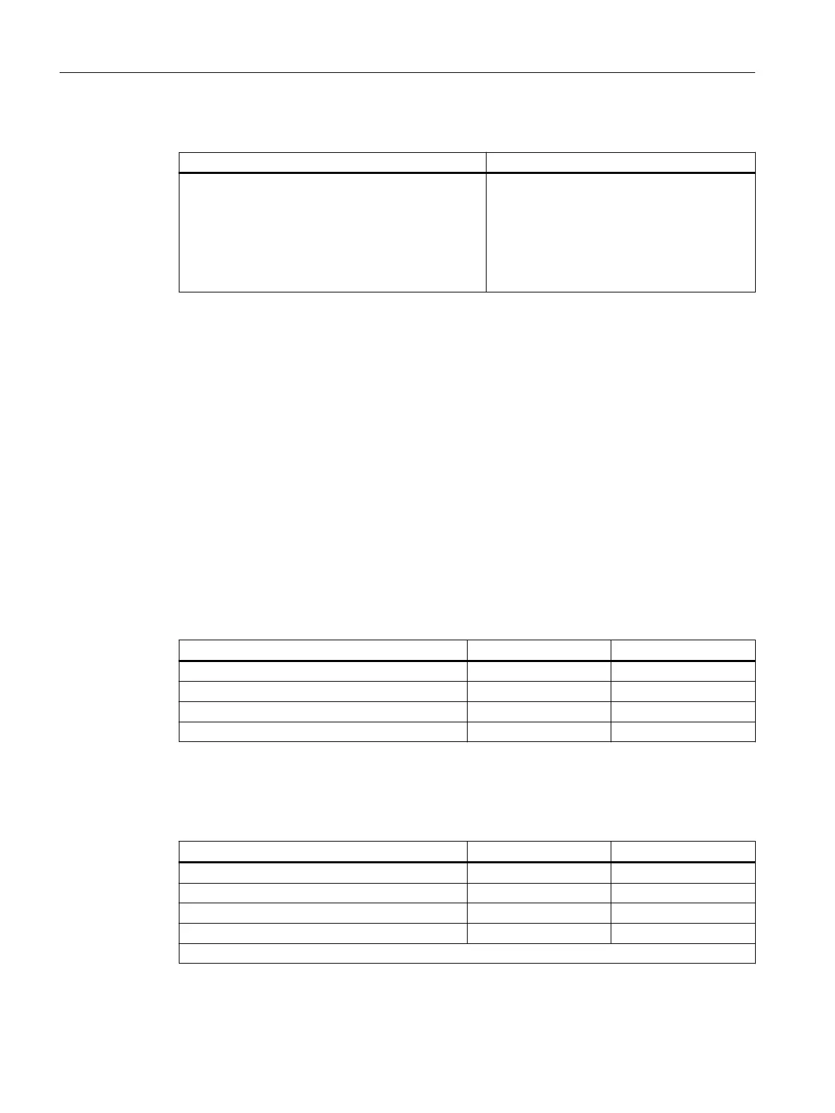
STEP 7 user program
STL Explanation
Call SFC 13
REQ :=TRUE
LADDR :=W#16#3FE
RET_VAL :=MW 0
RECORD :=P#DB82.DBX 0.0 BYTE 96
BUSY :=M2.0
Read request
Diagnostic address of the ET 200iSP
RET_VAL from SFC 13
Data compartment for the diagnostics in DB 82
Read process runs over several OB1 cycles
7.13.3 Diagnostic messages of the electronic modules with PROFIBUS
Introduction
You can set parameters for the diagnostic messages of the following modules:
• Digital input modules
• Digital output modules
• Analog input modules
• Analog output modules
Digital input modules
Table 7-20 Digital input modules
Diagnostic message Applicability Can be set
Short-circuit Channel Yes
Wire break Channel Yes
Error Module No
External fault Channel No
Digital output modules
Table 7-21 Digital output modules
Diagnostic message Applicability Can be set
Short-circuit Channel Yes
Wire break Channel Yes
Error Module No
Actuator disconnection Channel Yes
1
1
Enabling the actuator disconnection by means of the group diagnostics parameter
Commissioning and Diagnostics
7.13 Diagnostics with STEP 7 with PROFIBUS
ET 200iSP
198 Operating Instructions, 11/2022, A5E00247483-AK

 Loading...


