Commissioning Manual
6FC5397-4EP10-0BA8, 07/2018
113
There are holes through which you pass cables on both sides of the terminal box of 1PH1 motor. You can connect the
cables through the holes on any of the both sides. For more information about how to adjust cable orientations, see Section
"Connecting the terminal boxes of the 1PH1 motor (Page 113)".
Connecting the terminal boxes of the 1PH1 motor
Use of appropriate connecting cables
To reduce the risk of cable overheating and even overburning, appropriate cables are necessary for connecting the
terminal box.
• Carefully observe the current which the motor draws for your particular application. Adequately dimension the
connecting cables according to IEC 60204-1 or IEC 60364-5-52.
Damage to cables or connectors
•
Do not put much stress upon cables or connectors while wiring.
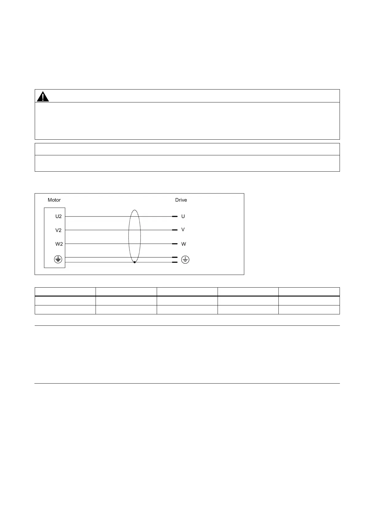
Power connection between the motor and the drive
Technical data for the fan of the 1PH1 motor
The recommended sequence for cable connections is as follows: encoder cable first, power cable next, and then the fan
cable.
There
are threaded holes available on both sides of the terminal box housing for you to pass the cables through. You can
select to connect the individual cables to the terminal boxes from the threaded holes on the desired side.
No fan cable is provided at delivery. When connecting your own fan cable, make sure you connect the fan terminals U,
V, and W correspondingly to the line supply terminals L1, L2, and L3 of the machine tool using appropriate cable

 Loading...


