Commissioning Manual
6FC5397-4EP10-0BA8, 07/2018
149
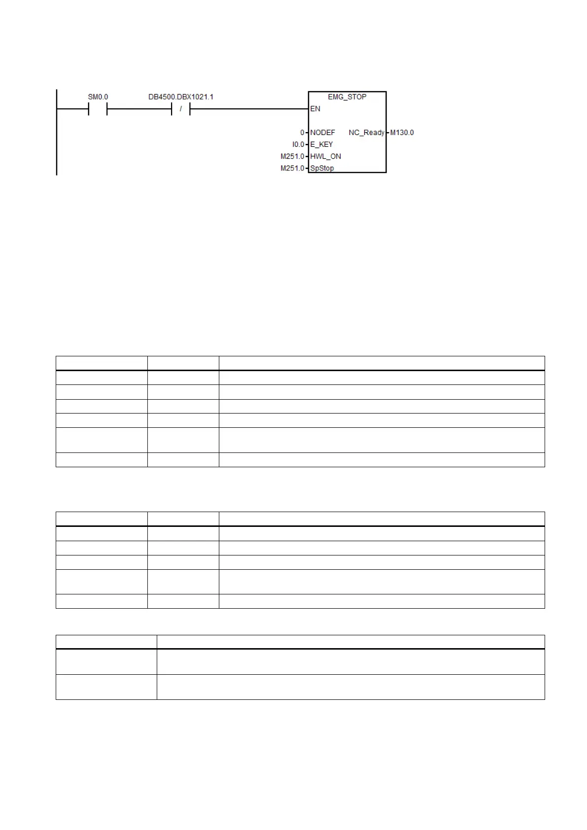
Example for calling subroutine 33
Subroutine 37 - MCP_NCK (MCP and HMI signal processing)
Purpose
Subroutine 37 is used to transfer the interface signals from the MCP and HMI to the NCK interfaces, and thus to activate the
specific operating mode and control sequences. It has the following main functions:
● Selecting specific operating mode
● Selecting override
● Transferring signals from the HMI to NCK interfaces (for instance, program control, handwheel, etc.)
● Controlling the axis traversing signal according to the PLC machine data
Local variable definition
Inputs
Define the Auxiliary Function Lock at the MCP key
1)
Define the Contour Handwheel at the MCP key
Define the simulation contour handwheel at the MCP key
NegDir-
BOOL Define the negative direction for simulation contour handwheel at the MCP key
Define the INCvar at the MCP key
When the Auxiliary Function Lock function is active, all the outputs caused by auxiliary functions (like T, M, or S code)
are disabled, only with the axis moving as usual.
Define the Auxiliary Function Lock at the MCP LED
Define the Contour Handwheel at the MCP LED
Define the simulation contour handwheel at the MCP LED
NegDir-
BOOL Define the negative direction for simulation contour handwheel at the MCP LED
Define the INCvar at the MCP LED
Relevant PLC machine data
14512 [20].0 Grey coded switch (0: spindle override controlled by the grey mode; 1: spindle override con-
trolled by trigger user keys)
14512 [20].2 Activate the first additional axis (0: disable the additional axis control; 1: enable the additional