Commissioning Manual
6FC5397-4EP10-0BA8, 07/2018
209
Note
This commissioning step is applicable to the standard axes only. For the drive configuration of ad
ditional axes, see Section
Configuring an additional feed axis (Page 234)".
Before starting the drive configuration, you must ensure the Drive Bus addresses are properly set (p0918) via the drive
BOPs. For more information about setting the Drive Bus address, refer to Section "Configuring Drive Bus addresses
(Page 118)".
Press this softkey on the main screen of drive configuration, and the control system starts to identify
the drives and motors con
nected. After the identification finishes, a drive list with motor information
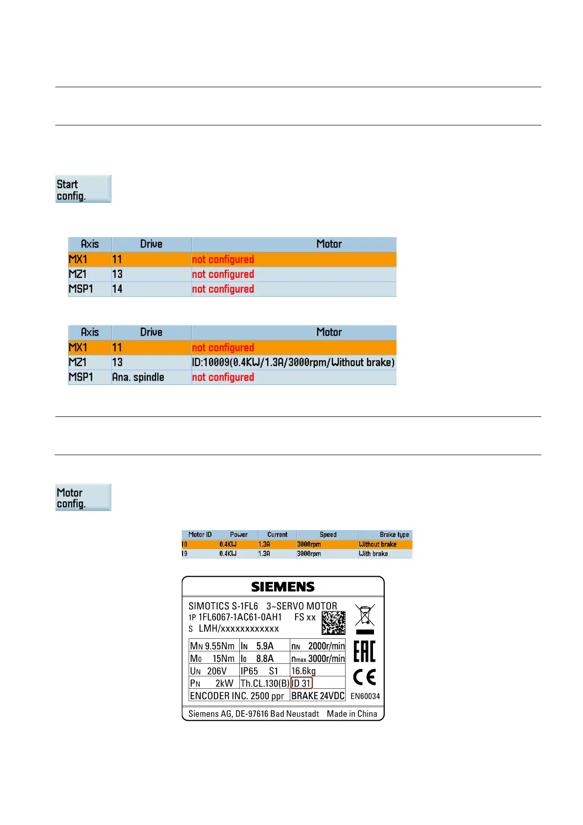
● If a V70 spindle drive is connected properly with the Drive Bus address set to 14, the control system identifies digital
spindle and displays as follows:
● If an analog spindle drive is connected through the PPU interface X54 and no V70 spindle drive is connected, the control
system identifies the analog spindle and displays as follows:
Configuring the feed axes
Note
This procedure is required only for a feed axis driven by a motor with an incremental encoder. If the sele
cted axis is
configured with a motor with an absolute encoder, the motor ID is identified automatically.
Select a feed axis using the cursor keys in the drive list window.
Press this softkey to open the motor configuration window.
Select the right motor ID with the cursor keys according to the motor rating plate.
For example, you can find the motor ID on the following motor rating plate:

 Loading...


