Commissioning Manual
6FC5397-4EP10-0BA8, 07/2018
279
Configuring the DSC function for the digital spindle
Function overview
The Dynamic Stiffness Control (DSC) function eliminates the deadtime that necessarily exists at the speed-setpoint interface
normally used between the NCK and drive due to relocation of the position controller into the drive.
To use the DSC function for the digital spindle, you must additionally connect an external spindle encoder via interface X60
in addition to the motor encoder and configure two measuring systems. For more information about interface X60, see
Section "Analog spindle interface - X54, spindle encoder interface - X60 (Page 88)".
Setting parameters for two measuring systems
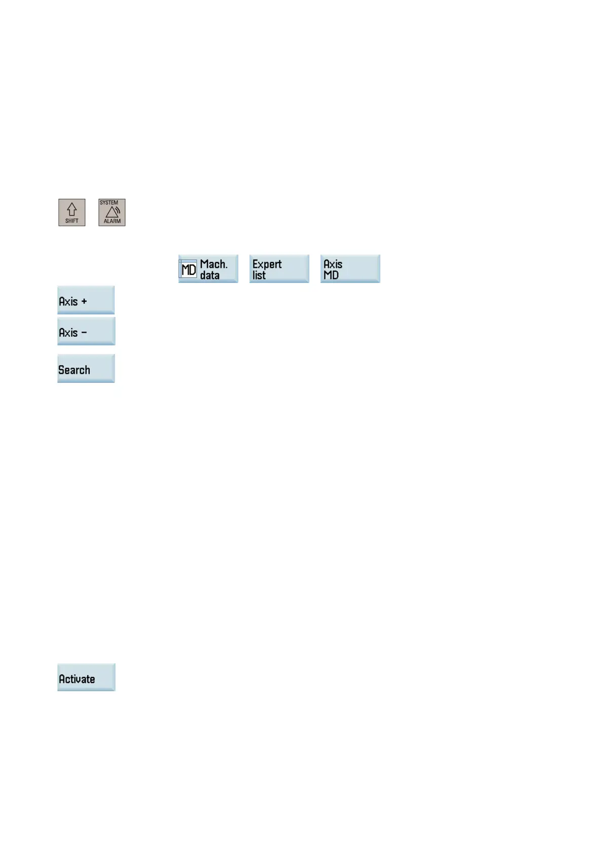
Select the system data operating area.
chine data window through the following softkey operations:
Use these softkeys to switch to the data set for the spindle (MSP1).
Use this softkey or the cursor keys to search for the followin
g machine data and assign the
30200 = 2
For the first measuring system (motor encoder):
– 30210[0] = 5
– 30220[0] = 4
– 30230[0] = 1
– 30240[0] = 1
– 31020[0] = resolution of the motor encoder
– 31040[0] = 0
– 31050[0] = load gearbox denominator
– 31060[0] = load gearbox numerator
For the second measuring system (external encoder):
– 30210[1] = 0
– 30220[1] = 4
– 30230[1] = 4
– 30240[1] = 2
– 31020[1] = resolution of the external spindle encoder
– 31040[1] = 1
– 31050[1] = load gearbox denominator
– 31060[1] = load gearbox numerator
– 36300[1] ≤ 2000000 (2 MHz which is the max. frequency of interface X60)
Press this softkey to activate the value changes. Note that the control sys
tem restarts to ac-
After finishing the parameter setting, you can activate the second measuring system by setting the following PLC user
interfaces (where the fourth axis is configured as spindle):
● DB3803.DBX1.5 = 0
● DB3803.DBX1.6 = 1

 Loading...


