Commissioning Manual
100 6FC5397-4EP10-0BA8, 07/2018
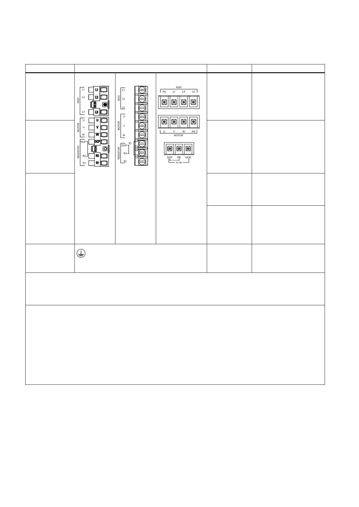
Main circuit interfaces
Main circuit interfaces (drive side)
Line supply input
interface
FSA:
FSB/FSC:
FSD:
Line phase L1
Line phase L2
Line phase L3
PE (protective
earth, for FSD
For connecting to the 3
phase 380 VAC to 480 VAC
power supply
Motor power inter-
face
Motor phase U
Motor phase V
Motor phase W
PE (For FSD
only)
•
necting to the
SIMOTICS S-1FL6 mo-
tor
• V70 spindle drive: for
connecting to the
SIMOTICS M-1PH1
Internal/external
braking resistor
interface
1)
DCP (DC posi-
tive)
R2 (resistor 2)
For connecting to an exter-
nal braking resistor, availa-
ble on V70 feed drive and
V70 spindle drive FSB/FSC
DCP
PB (power
brake)
DCN (DC nega-
For connecting to an exter-
nal braking resistor, availa-
ble on V70 spindle drive
FSD
Grounding con-
nector
PE For connecting the power
supply grounding connector
and the servo motor
Screw types and recommended tightening torques:
• FSA: M2.5 screws (0.4 Nm (3.54 lbf.in) to 0.5 Nm (4.43 lbf.in))
• FSB/FSC: M4 screws (2.25 Nm (19.93 lbf.in))
•
FSD: M5 screws (2.35 Nm (20.81 lbf.in))
Recommended minimum cross-section of the line supply cable:
• V70 feed drive:
– FSA: 1.5 mm
2
– FSB/FSC: 2.5 mm
2
• V70 spindle drive:
– FSB: 2.5 mm
2
– FSC: 4 mm
2
– FSD: 16 mm
2
For more information about how to assemble the terminals for the line supply cable, see Section "Assembling the line sup-
ply terminal for the drive (Page 459)".
The internal braking resistor is available only with the SINAMICS V70 feed drive.
2)
For SINAMICS V70 feed drives, DCP is connected to R2 at the factory with a short-circuit stick.

 Loading...


