13 Meters
100 PM5D/PM5D-RH Owner’s Manual Operating section
This chapter explains meter-related operations.
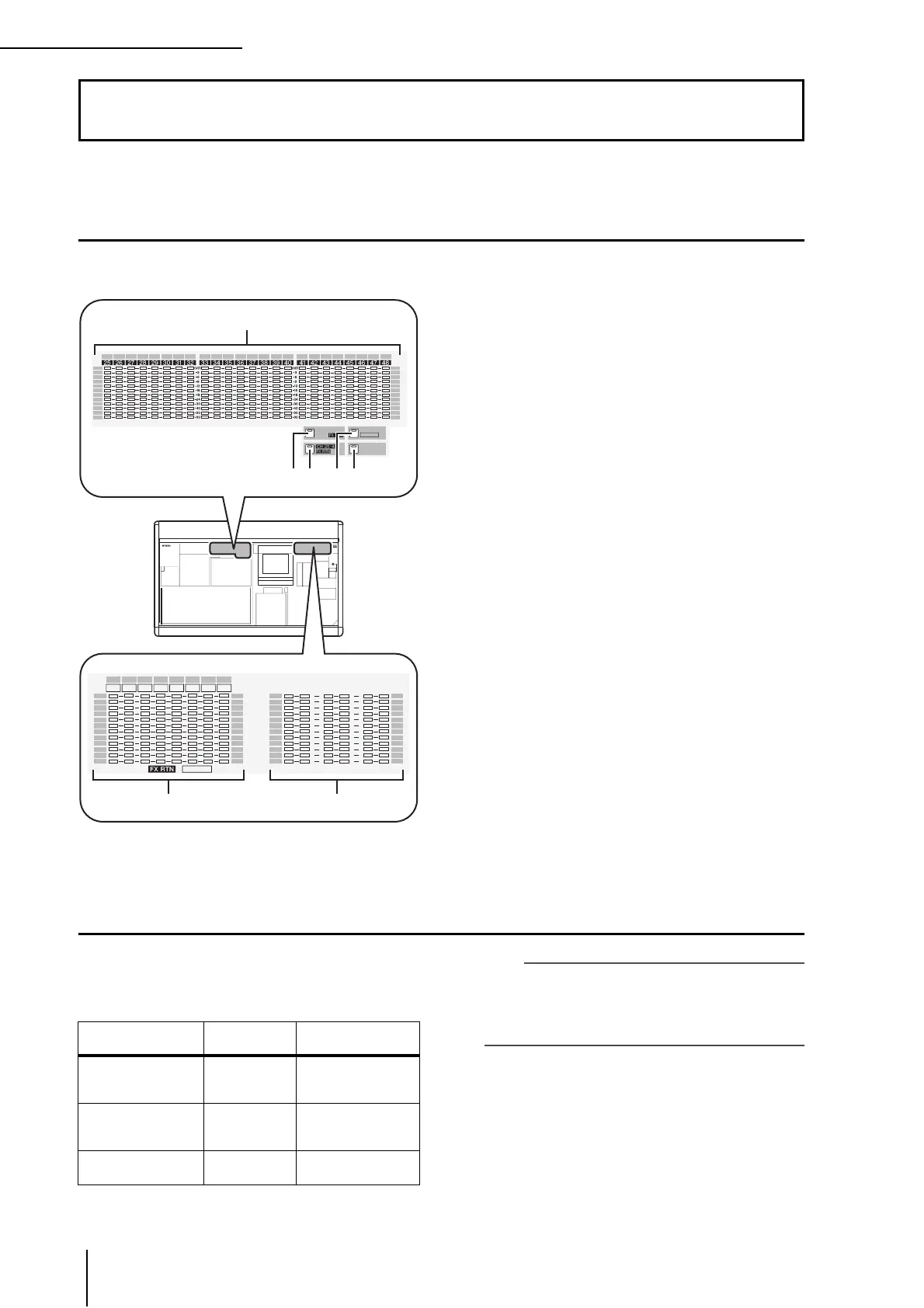
Items in the meter section
The meter section shows the input levels of the input channels and the output levels of the output channels.
A INPUT/MIX meters
Depending on the key you press, these meters indicate
the input levels of input channels 1–24 or 25–48, or the
output levels of MIX channels 1–24.
B [CH 1-24/ST IN/FX RTN] key
When this key is on, the INPUT/MIX meters indicate
the input levels of input channels 1–24 and the ST IN/
FX RTN/MATRIX meters indicate the output level of
ST IN channels (or FX RTN channels, depending on
the FOLLOW INPUT LAYER setting) 1–4.
C [CH 25-48/FX RTN/ST IN] key
When this key is on, the INPUT/MIX meters indicate
the input levels of input channels 25–48 and the ST IN/
FX RTN/MATRIX meters indicate the output level of
FX RTN channels (or ST IN channels, depending on
the FOLLOW INPUT LAYER setting) 1–4.
D [MIX/MASTER] key
When this key is on, the INPUT/MIX meters indicate
the output levels of MIX channels 1–24 and the ST IN/
FX RTN/MATRIX meters indicate the output levels of
MATRIX channels 1–8.
E [PEAK HOLD] key
Switches the peak hold function on/off for the meter
display.
F ST IN/FX RTN/MATRIX meters
Depending on the key you press, these meters indicate
the output levels of ST IN channels 1–4 or MATRIX
channels 1–8.
G MASTER meters
These meters always indicate the output levels of the
STEREO A/B channels and CUE bus.
Switching the meter display
You can use the keys of the meter section to specify the
channels whose levels will be shown in the INPUT/MIX
meters and ST IN/MATRIX meters. The following chan-
nels correspond to each key.
Hint
• The type of channels shown in the meter section is also
shown in the METER SECTION area in the upper right of
the display.
• The MASTER meters always indicate the output levels of
the STEREO A/B channels and CUE bus.
13 Meters
MIX
PEAK
HOLD
CH 1 -24
24
OVER
-3
-6
-9
-12
-15
-18
-24
-30
-40
-50
-60
OVER
-3
-6
-9
-12
-15
-18
-24
-30
-40
-50
-60
2322212019181716151413121110987654321
ST IN/
/ST IN
MATRIX
OVER
-3
-6
-9
-12
-15
-18
-24
-30
-40
-50
-60
OVER
-3
-6
-9
-12
-15
-18
-24
-30
-40
-50
-60
OVER
-3
-6
-9
-12
-15
-18
-24
-30
-40
-50
-60
OVER
-3
-6
-9
-12
-15
-18
-24
-30
-40
-50
-60
STEREO
A
STEREO
B CUE
LR LR LR
1L 1R 2L 2R 3L 3R 4L 4R
MATRIX
ST IN / /
1 2 3 4 5 6 7 8
1
32 54
6 7
Key
[INPUT/MIX]
meters
[ST IN/MATRIX]
meters
[CH 1-24/ST IN/FX
RTN] key
Input channels
1–24
ST channels
(or FX RTN channels)
1–4
[CH 25-48/FX RTN/
ST IN] key
Input channels
25–48
FX RTN channels
(or ST IN channels)
1–4
[MIX/MATRIX] key
MIX channels
1–24
MATRIX channels
1–8
 Loading...