PM5D/PM5D-RH Owner’s Manual Operating section 123
16
Remote control
Using GPI (General Purpose Interface)
The GPI connector on the rear panel can be used as a GPI (General Purpose Interface) input/output connector. This connec-
tor provides four GPI IN ports and twelve GPI OUT ports. For example you can use an external switch or joystick to control
the PM5D’s parameters, or conversely use the PM5D’s keys and faders to send control signals to an external device.
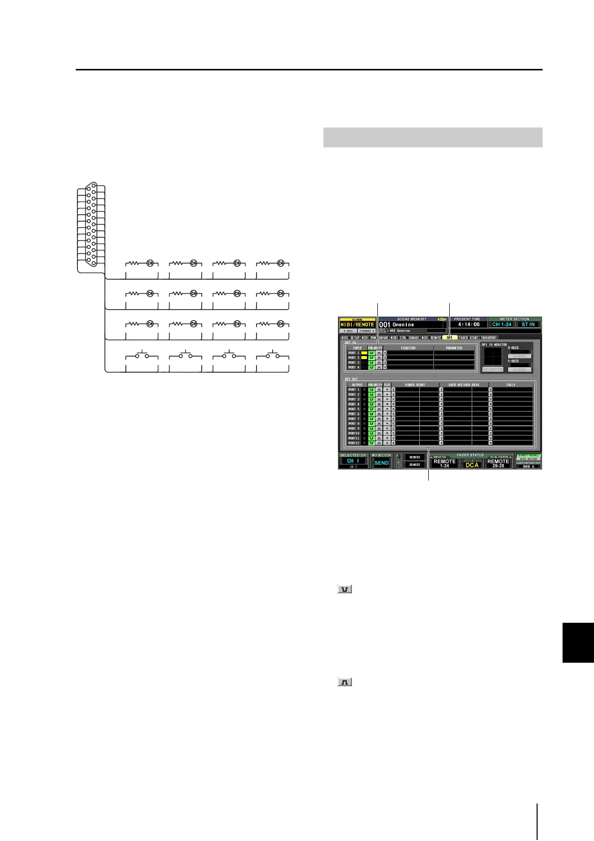
The following diagram is an example of an external circuit
that can operate GPI via the GPI connector. (For specifica-
tions of the GPI connector pins, refer to the Appendices
p.348 and p.355 at the end of the manual.)
This circuit uses four switches (GPI 1–GPI 4) to switch the
GPI IN ports between active and inactive. If the polarity of
a GPI OUT port is set to Low Active, and you operate the
PM5D to make the GPI OUT port Active, the correspond-
ing LED in the above circuit (GPO 1–GPO 12) will light.
(If the polarity of the GPI OUT port is High Active, the
LED will go dark.)
You can use the GPI IN ports of the GPI connector to con-
trol PM5D parameters from an external device. For
example you can use an external switch to turn the
PM5D’s talkback on/off or to operate its Tap Tempo func-
tion, or you can use a joystick to control surround
panning.
1
Connect an external device to the PM5D’s GPI
connector.
2
In the DISPLAY ACCESS section, press the
[MIDI/REMOTE] key several times to access the
GPI screen shown below.
In this screen, the upper list is used to make GPI IN
settings and the lower list is used to make GPI OUT
settings.
3
In the POLARITY column of the GPI IN list,
select the polarity of each GPI IN port.
You can select one of the following as the polarity for a
GPI IN port.
• (Low active)
When controlling an on/off switch-type parameter, the
port will become active when the switch is grounded.
When controlling a continuously-variable parameter,
that parameter will be at its maximum value when the
voltage is at low level (by default, 0V), and at its mini-
mum value when the voltage is at high level (by default,
approximately 5V).
• (High active)
When controlling an on/off switch-type parameter, the
port will be active when the switch is opened or when a
high-level voltage is input.
9 1 21 14 9 2 21 15
GPO 1 GPO 2 GPO 3 GPO 4
9 3 21 16 9 4 21 17
GPO 5 GPO 6 GPO 7 GPO 8
21 24 9 12 21 25 9 13
GPO 9 GPO 10 GPO 11 GPO 12
14
15
16
17
18
19
20
21
22
23
24
25
2
3
4
5
6
7
8
9
10
11
12
13
1
GPI 1 GPI 2
GPI 3 GPI 4
22 18 10 6 23 19 11 7
Using GPI IN
GPIGPI IN list
GPI OUT list
 Loading...