PM5D/PM5D-RH Owner’s Manual Reference section 157
Information shown
in the display
Function
menu
Global
functions
Output
functions
Input
functions
Appendices
Note
• If the ASSIGN TO FADERS buttons A–F are off, you can
hold down the [SHIFT] button on the panel and press a
FADER MODE section button [A]–[F], and then use the DCA
faders to control the corresponding region of the graphic EQ
in the same way as if you had pressed a button A–F in the
screen.
• The currently selected DCA fader mode (DCA, A–F) is dis-
abled while one of the ASSIGN TO FADERS buttons A–F is
on. At this time, you can also use the FADER MODE sec-
tion buttons [A]–[F] to switch between regions of the graphic
EQ; the button for the selected region will blink, and the
remaining buttons will light.
• The setting in the ASSIGN TO FADERS area is defeated
when you switch screens; the currently selected DCA fader
mode will again be applied.
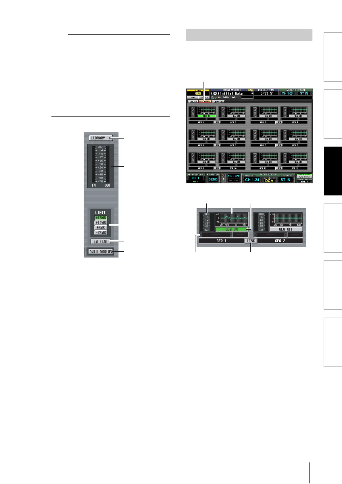
K LIBRARY
This button accesses the GEQ LIBRARY screen.
L Level meter
This meter indicates the peak level before and after the
graphic EQ.
M LIMIT
The range and direction of adjustment controlled by
the faders can be selected from the following: ±15 dB,
±12 dB, ±6 dB (these are valid in both the boost and
cut directions), or –24 dB (valid only in the cut
direction).
N EQ FLAT
Resets all faders to the 0 dB position. When you click
this button, a confirmation message will appear.
O AUTO ASSIGN
This button automates assignments to the DCA faders.
If this button is on, the most recently selected region of
GEQ bands will be assigned to the DCA faders when
you access the GEQ PARAM screen.
This screen lists the approximate values of the graphic EQ
settings, and shows the input/output levels. The signal path
assignments and on/off status can also be edited in this
screen.
A Level meter
This meter indicates the peak level before and after the
graphic EQ.
B Fader graph
This indicates the approximate fader position for each
band. When you click this area, the GEQ PARAM
screen for the corresponding GEQ module will appear.
You can also drag and drop this area onto another
GEQ module to copy the GEQ settings.
C GEQ ON/OFF button
Switches the graphic EQ module on/off.
D Insert destination
Indicates the location at which the graphic EQ module
is inserted. You can also specify the insert location
from within this screen.
E LINK button
This button indicates the link status of adjacent odd-
numbered → even-numbered graphic EQ modules.
When you turn this button on, a window will appear,
allowing you to select whether the parameters will be
copied from one module to the other, or whether both
modules will be initialized.
K
L
M
N
O
GEQ ASSIGN screen
 Loading...