Effects Parameters
298 PM5D/PM5D-RH Owner’s Manual Reference section
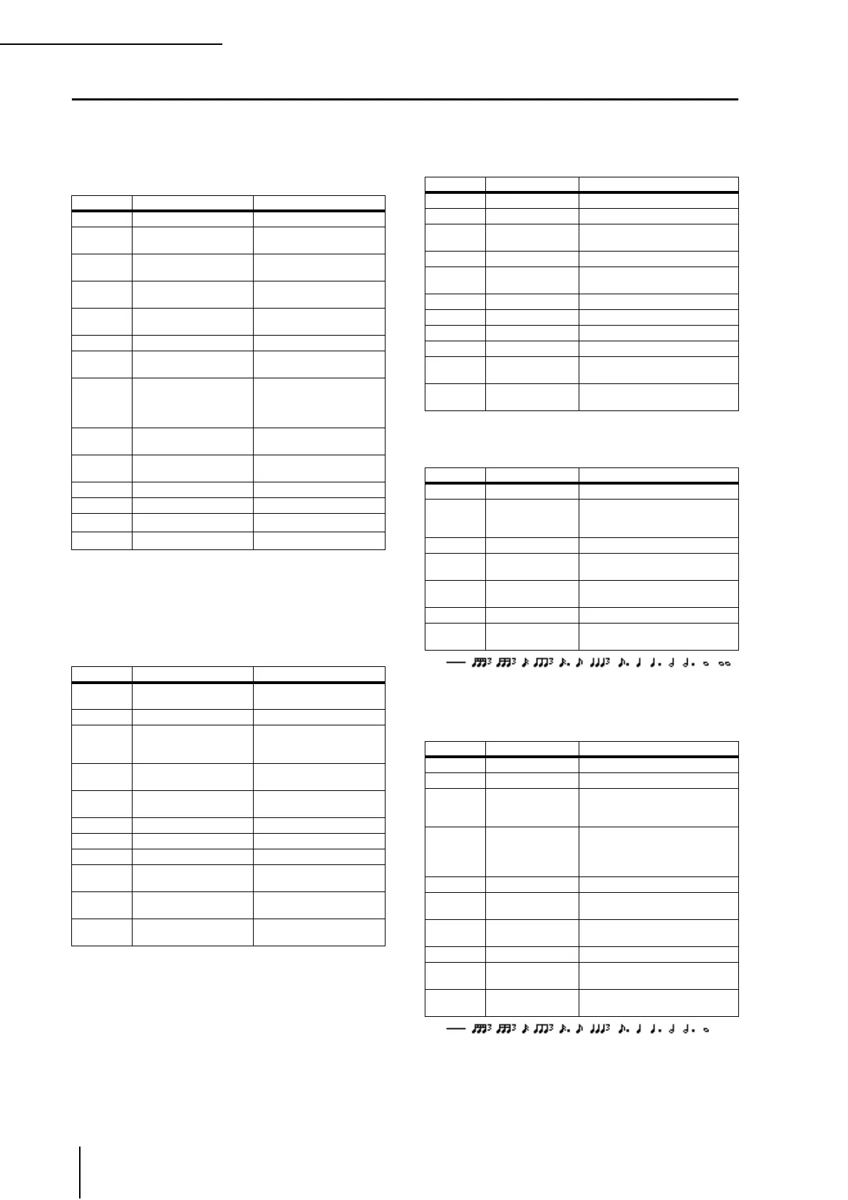
Effects Parameters
❏ REVERB HALL, REVERB ROOM, REVERB
STAGE, REVERB PLATE
One input, two output hall, room, stage, and plate reverb
simulations, all with gates.
❏ EARLY REF.
One input, two output early reflections.
❏ GATE REVERB, REVERSE GATE
One input, two output early reflections with gate, and early
reflections with reverse gate.
❏ MONO DELAY
One input, one output basic repeat delay.
❏ STEREO DELAY
Two input, two output basic stereo delay.
Parameter Range Description
REV TIME 0.3–99.0 s Reverb time
INI. DLY 0.0–500.0 ms
Initial delay before reverb
begins
HI. RATIO 0.1–1.0
High-frequency reverb time
ratio
LO. RATIO 0.1–2.4
Low-frequency reverb time
ratio
DIFF. 0–10
Reverb diffusion (left–right
reverb spread)
DENSITY 0–100% Reverb density
E/R DLY 0.0–100.0 ms
Delay between early reflec-
tions and reverb
E/R BAL. 0–100%
Balance of early reflections
and reverb
(0% = all reverb, 100% = all
early reflections)
HPF THRU, 21.2 Hz–8.00 kHz
High-pass filter cutoff fre-
quency
LPF 50.0 Hz–16.0 kHz, THRU
Low-pass filter cutoff fre-
quency
GATE LVL OFF, –60 to 0 dB Level at which gate kicks in
ATTACK 0–120 ms Gate opening speed
HOLD
*1
*1. 0.02 ms–2.13 s (fs=44.1 kHz), 0.02 ms–1.96 s (fs=48 kHz),
0.01 ms–1.06 s (fs=88.2 kHz), 0.01 ms–981 ms (fs=96 kHz)
Gate open time
DECAY
*2
*2. 6.0 ms–46.0 s (fs=44.1 kHz), 5.0 ms–42.3 s (fs=48 kHz),
3 ms–23.0 s (fs=88.2 kHz), 3 ms–21.1 s (fs=96 kHz)
Gate closing speed
Parameter Range Description
TYPE
S-Hall, L-Hall, Random,
Revers, Plate, Spring
Type of early reflection sim-
ulation
ROOMSIZE 0.1–20.0 Reflection spacing
LIVENESS 0–10
Early reflections decay char-
acteristics (0 = dead, 10 =
live)
INI. DLY 0.0–500.0 ms
Initial delay before reverb
begins
DIFF. 0–10
Reflection diffusion (left–
right reflection spread)
DENSITY 0–100% Reflection density
ER NUM. 1–19 Number of early reflections
FB GAIN –99 to +99% Feedback gain
HI. RATIO 0.1–1.0
High-frequency feedback
ratio
HPF THRU, 21.2 Hz–8.00 kHz
High-pass filter cutoff fre-
quency
LPF 50.0 Hz–16.0 kHz, THRU
Low-pass filter cutoff fre-
quency
Parameter Range Description
TYPE Type-A, Type-B Type of early reflection simulation
ROOMSIZE 0.1–20.0 Reflection spacing
LIVENESS 0–10
Early reflections decay characteris-
tics (0 = dead, 10 = live)
INI. DLY 0.0–500.0 ms Initial delay before reverb begins
DIFF. 0–10
Reflection diffusion (left–right
reflection spread)
DENSITY 0–100% Reflection density
HI. RATIO 0.1–1.0 High-frequency feedback ratio
ER NUM. 1–19 Number of early reflections
FB GAIN –99 to +99% Feedback gain
HPF
THRU, 21.2 Hz–
8.00 kHz
High-pass filter cutoff frequency
LPF
50.0 Hz–16.0 kHz,
THRU
Low-pass filter cutoff frequency
Parameter Range Description
DELAY 0.0–2730.0 ms Delay time
FB. GAIN –99 to +99%
Feedback gain (plus values for
normal-phase feedback, minus
values for reverse-phase feedback)
HI. RATIO 0.1–1.0 High-frequency feedback ratio
HPF
THRU, 21.2 Hz–
8.00 kHz
High-pass filter cutoff frequency
LPF
50.0 Hz–16.0 kHz,
THRU
Low-pass filter cutoff frequency
SYNC OFF/ON Tempo parameter sync on/off
NOTE
*1
*1. (
Max. value depends on tempo setting)
Used in conjunction with TEMPO
to determine DELAY
Parameter Range Description
DELAY L 0.0–1350.0 ms Left channel delay time
DELAY R 0.0–1350.0 ms Right channel delay time
FB. G L –99 to +99%
Left channel feedback (plus values
for normal-phase feedback, minus
values for reverse-phase feedback)
FB. G R –99 to +99%
Right channel feedback (plus val-
ues for normal-phase feedback,
minus values for reverse-phase
feedback)
HI. RATIO 0.1–1.0 High-frequency feedback ratio
HPF
THRU, 21.2 Hz–
8.00 kHz
High-pass filter cutoff frequency
LPF
50.0 Hz–16.0 kHz,
THRU
Low-pass filter cutoff frequency
SYNC OFF/ON Tempo parameter sync on/off
NOTE L
*1
*1.
(Maximum value depends on the tempo setting)
Used in conjunction with TEMPO
to determine left channel DELAY
NOTE R 1
Used in conjunction with TEMPO
to determine right channel DELAY
 Loading...