PM5D/PM5D-RH Owner’s Manual Reference section 231
Information shown
in the display
Function
menu
Global
functions
Output
functions
Input
functions
Appendices
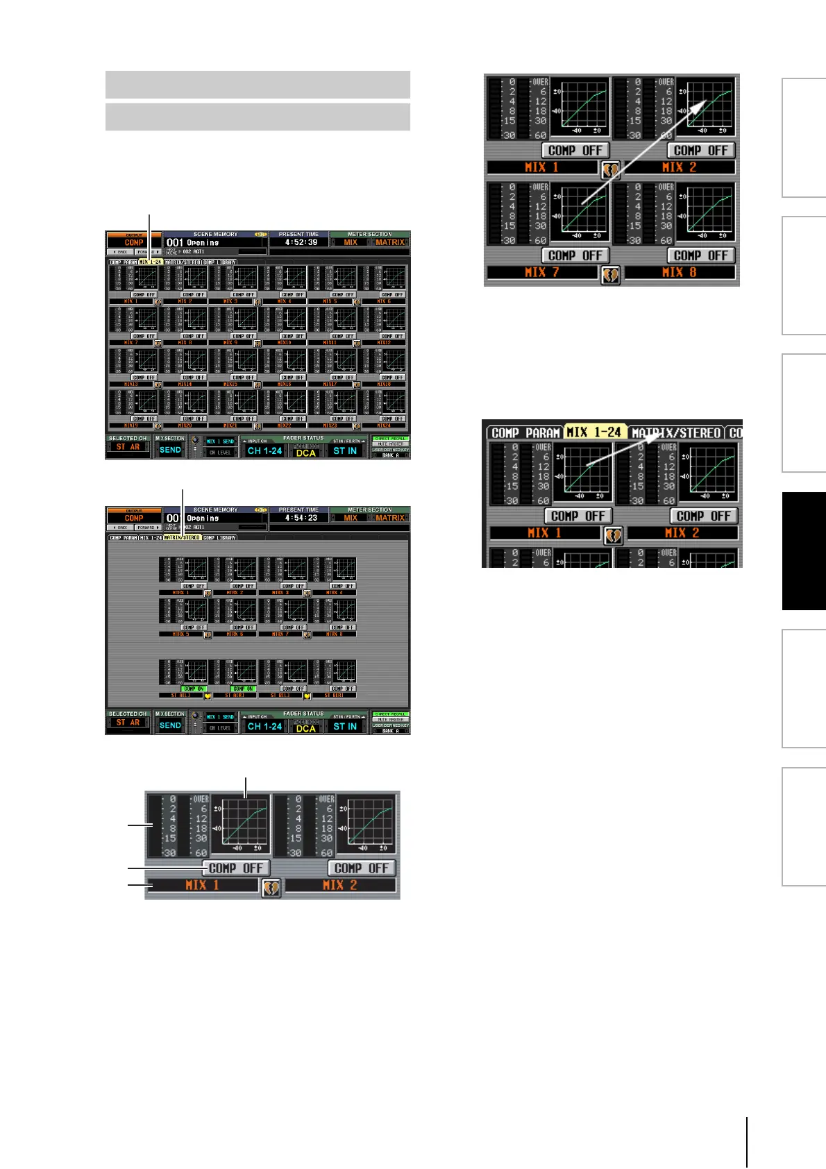
These screens show the compressor settings for all output
channels. Here you can also copy compressor settings
between output channels.
A Compressor graph
This mini-graph shows the approximate compressor
response for each output channel.
When you click the graph at which the cursor is cur-
rently located, the COMP PARAM screen for that
channel will appear.
In this screen you can drag and drop the mini-graph
from the desired channel to copy its compressor set-
tings. (When you drag and drop the mini-graph, a
popup window will ask you to confirm the copy
operation.)
You can also copy compressor settings between the
MIX 1-24 screen and the MATRIX/STEREO screen.
First drag the mini-graph over the MIX 1-24 tab or
MATRIX/STEREO tab in the screen (the screen will
switch). Then drag and drop the mini-graph onto the
desired channel, and a message will ask you to confirm
the copy operation.
B Level meters
These meters show the amount of gain reduction pro-
duced by the compressor (at left), and the peak level of
the signal after passing through the compressor (at
right). If the signal clips, the OVER segment will light.
C COMP ON/OFF (Compressor on/off)
Turns the compressor on/off for that channel.
D Channel
This is the number of the channel you are editing. Two
paired channels are indicated by a heart symbol dis-
played between them.
MIX 1-24 screen
MATRIX/STEREO screen
MIX 1-24
MATRIX/STEREO
4
2
3
 Loading...