PAN/ROUTING function
274 PM5D/PM5D-RH Owner’s Manual Reference section
PAN/ROUTING function
Here you can send signals from input channels to the
desired MIX bus. In this screen you can also switch the
type (VARI or FIXED) of each MIX bus, and specify the
location from which the signal will be sent.
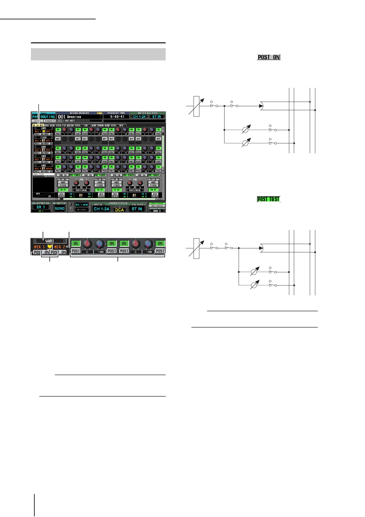
A Type selection
Here you can select the mix bus type for every two
adjacent odd-numbered/even-numbered MIX buses.
You can choose one of the following types.
• FIXED
The send level of the MIX bus is fixed at nominal level
(0.0 dB). Choose this if you want to use the MIX bus as
a group output or as a bus output for recording on a
multitrack recorder.
• VARI (Variable)
The send level of the MIX bus is adjustable. Choose
this if you want to use the MIX bus as an external effect
send or as a foldback output.
Hint
If surround mode is enabled, the type indication will change to
“SURROUND” for MIX buses used as surround buses. You
cannot change the mix bus type during this time.
B MIX bus
This is the number of the MIX bus to which the signal
is sent. Paired MIX buses are indicated by a heart sym-
bol displayed between them. You can click this symbol
to enable/disable pairing.
C POST ON/POST TO ST (Post on / Post to
stereo)
This button lets you specify in greater detail the loca-
tion from which post-fader signals will be sent from
input channels to this MIX bus. You can choose one of
the following two send locations.
❏ POST ON
The signal will be sent from immediately after the
[ON] key.
POST ON/POST TO ST=
❏ POST TO ST
The signal will be sent from immediately after the [TO
STEREO] key.
POST ON/POST TO ST=
Hint
This setting applies to the signals sent from all input channels
to the corresponding MIX bus.
D CH to MIX (Channel to mix)
In this area, the signals sent from input channels / ST
IN channels (vertical columns) to MIX buses (horizon-
tal rows) can be switched on/off and their level
adjusted.
The buttons and knobs displayed here will differ
depending on the type (FIXED or VARI) of the send-
destination MIX bus, and on whether the MIX buses
are paired.
CH to MIX (Channel to mix) screen
CH to MIX
MIX1
MIX2
STEREO L
STEREO R
……
……
FADER
INPUT CHANNEL 1
ON TO ST
ON
ON
PAN
MIX1 (VARI)
LEVEL
MIX2 (VARI)
LEVEL
MIX1
MIX2
STEREO L
STEREO R
……
……
FADER
INPUT CHANNEL 1
ON TO ST
ON
ON
PAN
MIX1 (VARI)
LEVEL
MIX2 (VARI)
LEVEL
 Loading...