MATRIX/ST function
240 PM5D/PM5D-RH Owner’s Manual Reference section
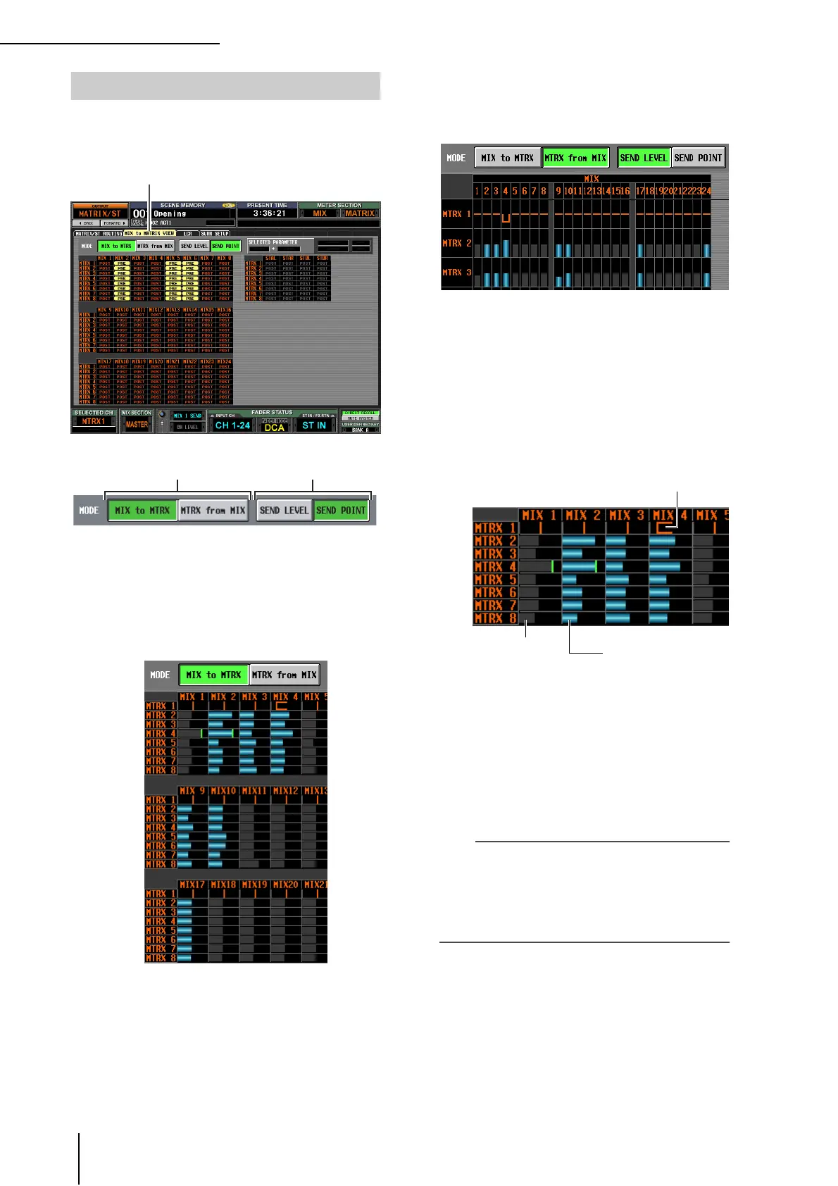
This screen lists the signals sent from the MIX channels to
the MATRIX buses. You can also edit the settings from
within this screen.
A MIX to MTRX/MTRX from MIX
Select one of the following two types of screen display.
❏ When the MIX to MTRX button is on
You can view the status of the signals sent from a spe-
cific MIX channel or STEREO A/B channel to all
MATRIX buses.
❏ When the MTRX from MIX button is on
You can view the status of the signals sent from all MIX
channels or STEREO A/B channels to a specific
MATRIX bus.
B SEND LEVEL/SEND POINT
Select one of the following two parameters to view in
the grid.
❏ When the SEND LEVEL button is on
The send levels sent from the MIX channels or STE-
REO A/B channels to the MATRIX buses will be shown
as a bar graph in each grid. Channels for which the sig-
nal sent to the MATRIX bus is turned off are shown by
gray bars, and channels for which the signal is turned
on are shown by blue bars.
To edit the send level, move the cursor to the grid
where the MIX or STEREO A/B channel (vertical col-
umn) intersects the MATRIX bus (horizontal row),
and turn the [DATA] encoder.
To switch the signal sent from a specific MIX or STE-
REO A/B channel to the MATRIX buses on/off, move
the cursor to the vertical column for that channel, and
press the [ENTER] key.
Hint
• If the send level is set above nominal (0 dB), a red line indi-
cating nominal level is displayed.
• If the send-destination MATRIX channel is paired, the grid
for the odd-numbered MATRIX bus will show an orange line
indicating the pan value instead of a bar graph. (In MTRX
from MIX mode, upward indicates R, and downward indi-
cates L.)
If the SEND LEVEL button is on, you can select a
desired grid and copy its send level (pan) value to other
channels (horizontal direction) or to other MATRIX
buses (vertical direction), or switch all grids on/off
simultaneously.
To do so, move the cursor to the desired grid; then
hold down the [SHIFT] key and press the [ENTER]
key. (Alternatively, hold down the [SHIFT] key and
click the desired grid.) When the JOB SELECT win-
MIX to MATRIX VIEW screen
MIX to MATRIX VIEW
Channels for which the
signal sent to the MATRIX
bus is turned on (blue bar
graph)
Channels for which the
signal sent to the MATRIX
bus is turned off (gray bar
graph)
Pan value (orange line)
 Loading...