PM5D/PM5D-RH Owner’s Manual Reference section 221
Information shown
in the display
Function
menu
Global
functions
Output
functions
Input
functions
Appendices
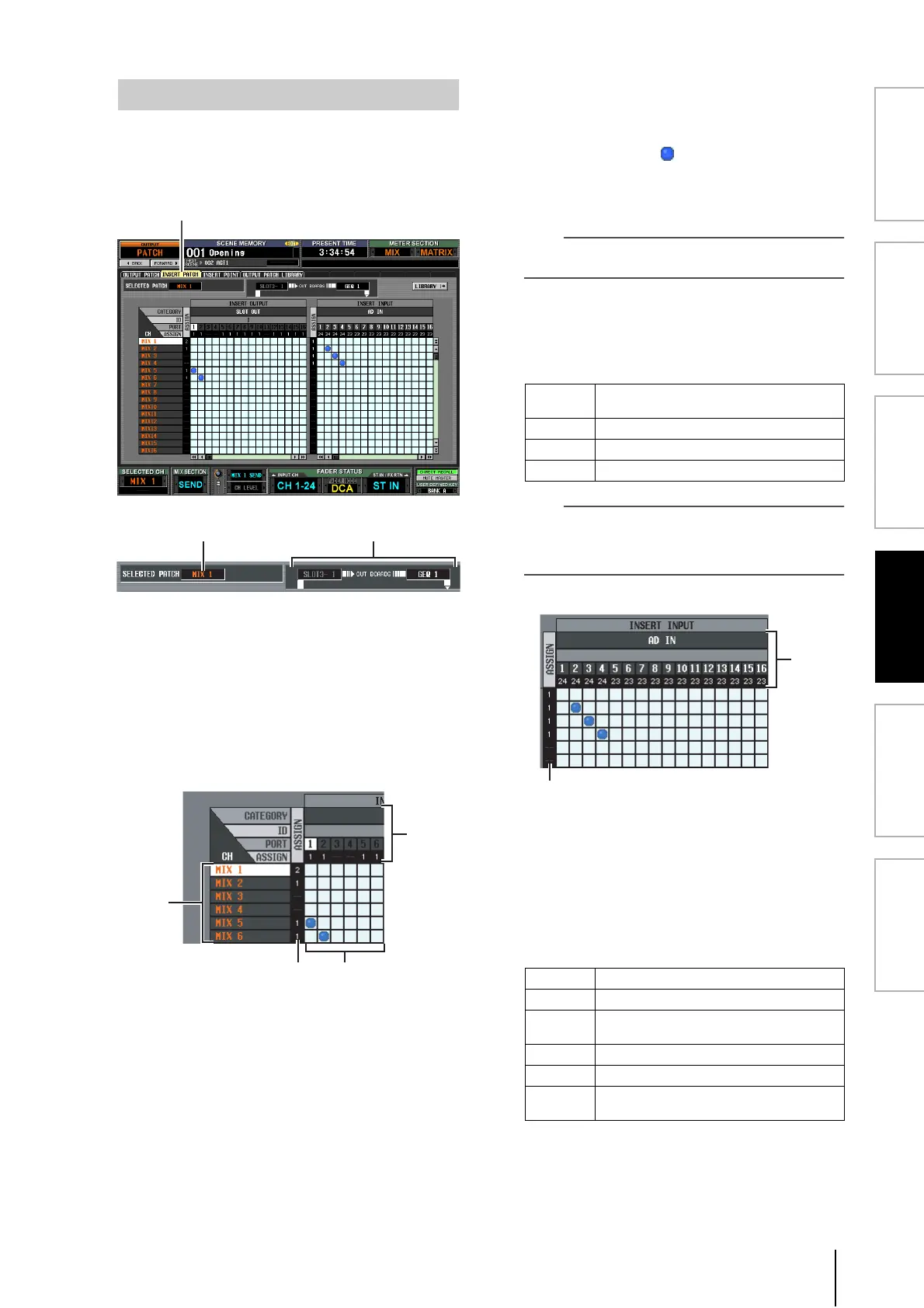
In this screen you can patch the input/output ports into
which external devices will be inserted. Select the output
port in the left side of the screen, and the input port in the
right side of the screen.
A SELECTED PATCH
This indicates the number of the output channel at
which the cursor is located in the grid.
B Insert in/out
This indicates the input/output ports that are patched
as insert in/out for the output channel at which the
cursor is located. If multiple ports are assigned for
insert-out, only the first port is displayed.
C CH (Output channel)
This area shows the numbers of the output channels
(MIX channels, MATRIX channels, STEREO A/B
channels, MONITOR L/R/C channels). The channel
number at which the cursor is located will be
highlighted.
D ASSIGN
For each output channel, this indicates the number of
output ports that are currently assigned as insert-out.
E Grid
For each output channel (vertical column), this grid
lets you can patch one or more output ports (horizon-
tal row) to be used as insert-outs. Currently-patched
grids are indicated by a symbol.
By clicking a grid location you can set/cancel patching.
The red lines at the left and top indicate the grid loca-
tion to which you move the cursor.
Hint
Operations in the grid are the same for all of the patching
screens. For details, refer to the Hint on p.220.
F Output port
From the top, this area indicates the type of output
port, the ID number, the output channel number, and
the number of output channels assigned. The follow-
ing types of output port can be patched as insert-out.
Hint
If you select FX IN as an insert-out, the output of the same
internal effect will automatically be selected as the insert-in. If
you select GEQ IN, the output of the same GEQ module will
automatically be selected as the insert-in.
G ASSIGN
For each input channel, this indicates the number of
input ports that are currently assigned as insert-in.
H Input port
From the top, this area indicates the type of input port,
the ID number, the input channel number, and the
number of input channels assigned. The following
types of input port can be selected.
INSERT PATCH screen
INSERT PATCH
6
3
45
SLOT OUT
Output channels of an I/O card installed in slots
1–4
FX IN L/R inputs of internal effects 1–8
GEQ IN Inputs of internal GEQ modules 1–12
2TR OUT L/R channels of 2TR OUT DIGITAL jacks 1–3
AD IN INPUT jacks 1–48
AD ST IN ST IN jacks 1–4 L/R
SLOT IN
Input channels of an I/O card installed in slots
1–4
FX OUT L/R outputs of internal effects 1–8
GEQ OUT Outputs of GEQ modules 1–12
2TR IN
L/R channels of 2TR IN DIGITAL jacks 1–3 and
2TR IN ANALOG jacks 1/2
8
7
 Loading...