PM5D/PM5D-RH Owner’s Manual Reference section 287
Information shown
in the display
Function
menu
Global
functions
Output
functions
Input
functions
Appendices
J DCA group / Mute group
K Recall safe / Mute safe
Refer to the explanation of the OUTPUT VIEW func-
tion CH VIEW screen (➥ p.246).
L DIRECT
Turns direct output on/off for the corresponding input
channel.
M INSERT
Turns insert on/off for the corresponding input
channel.
N SURROUND (Surround pan)
If surround mode is enabled, the surround pan posi-
tion of the corresponding input channel is indicated by
the O symbol in the surround pan grid and also as a
front/rear/left/right coordinate position. If you click
the surround pan grid, the SURR PARAM screen for
that channel will appear.
O LCR
Here you can switch LCR mode on/off, and adjust CSR
(the level of the CENTER channel relative to the L/R
channels) (➥ p.242).
P LIBRARY
This button accesses the INPUT CH LIBRARY screen
(➥ p.289), where you can store/recall input channel
library settings.
Q Level meter
This level meter indicates the input level of the channel.
R Signal detection point
This is the point at which the signal level shown in the
level meter (
S) is detected (PRE ATT, PRE GATE,
PRE FADER, POST FADER, or POST ON). You can
edit this setting by clicking the / buttons at the left
and right.
S Fader
This controls the input level of the channel.
T CUE
U ON/OFF (Channel on/off)
Refer to the explanation of the OUTPUT VIEW func-
tion CH VIEW screen (➥ p.247).
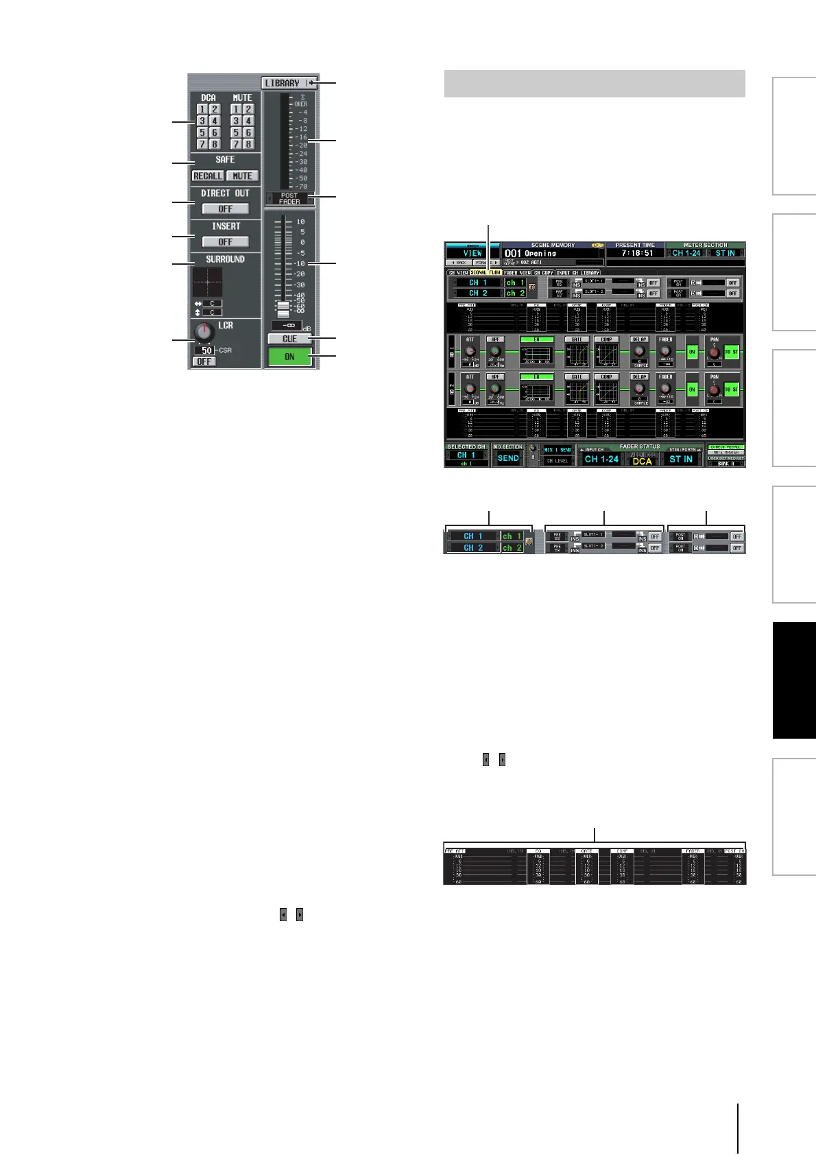
This screen shows the signal flow for two adjacent odd-
numbered/even-numbered input channels or ST IN chan-
nels. In this screen you can also edit some of the
parameters, and access other screens. You can also deter-
mine the location within the signal flow at which clipping
occurred.
A Channel
B Insert
Except for the fact that this screen depicts input chan-
nels, the contents are the same as the OUTPUT VIEW
function SIGNAL FLOW screen. Refer to p.247.
C Direct out
This area displays information about the direct output
of the two selected channels (the signal output posi-
tion, the port patched to direct out, and the direct
output on/off status).
Here you can also select the signal output position (use
the / buttons at left and right), and switch direct
output on/off (use the ON/OFF button).
D Level meters
These meters indicate the levels at various points in the
signal flow. Levels are detected at the following
locations.
• PRE ATT (immediately before the attenuator)
• EQ (immediately before and after the EQ)
• GATE (immediately before and after the gate)
• COMP (immediately before and after the
compressor)
• FADER (immediately before and after the fader)
K
J
L
M
N
O
P
Q
R
S
T
U
SIGNAL FLOW screen
 Loading...