INPUT PATCH function
256 PM5D/PM5D-RH Owner’s Manual Reference section
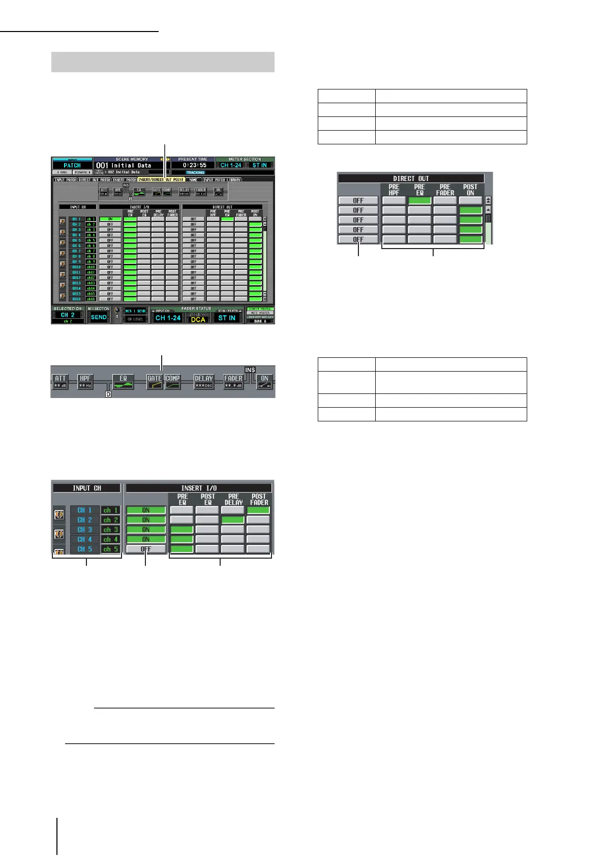
For each input channel, you can specify the point at which
insert in/out will be patched, and the point from which
direct output will be taken. Here you can also switch Insert
or Direct Output on/off.
A Insert view
When you move the cursor to an insert I/O point (4),
the insert and direct output locations for that input
channel will be shown graphically.
B INPUT CH (Input channel)
This is the number of the input channel you are edit-
ing. Two paired channels are indicated by a heart
symbol shown at the left; settings
3–6 will be linked
for these channels. You can click this symbol to enable/
disable pairing.
C INSERT ON/OFF
This button switches insert on/off for each channel.
This is linked for two paired channels.
Note
Be aware that if you turn on this button when either insert-in or
insert-out are unpatched, the signal will no longer be output
from the corresponding input channel.
D INSERT I/O (Insert I/O point)
Here you can select one of the following as the insert-
in/out location for each channel.
E DIRECT OUT ON/OFF
These buttons switch direct output on/off for each
channel.
F DIRECT OUT
Here you can select one of the following as the direct
output location for each channel.
INSERT/DIRECT OUT POINT screen
INSERT/DIRECT OUT POINT
PRE EQ Immediately before the EQ
POST EQ Immediately after the EQ
PRE DELAY Immediately before the delay
POST FADER Immediately after the fader
PRE HPF Immediately before the high-pass filter
PRE EQ
Immediately before the EQ (immediately
after the PRE EQ of the INSERT I/O)
PRE FADER Immediately before the fader
POST ON Immediately after the CH [ON] key
 Loading...