OUTPUT DCA/GROUP function
234 PM5D/PM5D-RH Owner’s Manual Reference section
OUTPUT DCA/GROUP func-
tion
Here you can specify the output channels that will be
assigned to DCA groups 7/8. You can use DCA faders 7/8
to uniformly adjust the levels of output channels belong-
ing to the same DCA group.
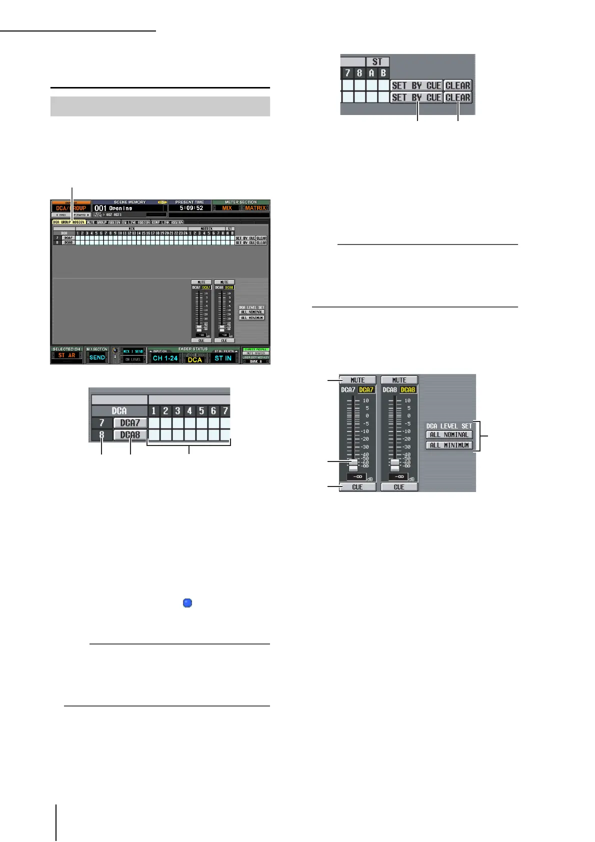
A DCA group
This is the number of the DCA group. The number
corresponding to the grid where the cursor is located is
highlighted.
B Name
This is the name of the DCA group. You can also click
this area to edit the name.
C Grid
This grid lets you assign output channels (horizontal
rows) to DCA groups (vertical columns). Currently-
patched grids are indicated by a symbol. Move the
cursor to the desired grid and press the [ENTER] key
(or click) to set/disable the assignment.
Hint
• You can also assign an output channel to both DCA groups
for multiple DCA control.
• DCA groups 1–6 are for input channels only, but DCA
groups 7/8 can be used with both input channels and output
channels. DCA groups 7/8 allow you to use both types of
channel in the identically-numbered group.
D SET BY CUE (Assign by [CUE] key)
This specifies whether the [CUE] key will be used to
make/cancel DCA group assignments. While the DCA
group SET BY CUE button is on, pressing the [CUE]
key of a channel that can be assigned to the corre-
sponding group will assign the channel to the group.
(Press the [CUE] key once again to cancel the
assignment.)
Hint
• The SET BY CUE button can be turned on for only one DCA
group. This is automatically turned off when you change
screens or turn off the power.
• To turn on SET BY CUE from the panel, press the ASSIGN
MODE [DCA] key and then turn on the DCA group 7/8
[CUE] key.
E CLEAR
This button clears all output channels assigned to that
DCA group.
F MUTE
These buttons switch muting on/off for DCA groups 7/
8. They are linked with DCA [MUTE] keys 7/8 in the
DCA strip of the panel.
G DCA faders
These faders adjust the levels of DCA groups 7/8. They
are linked with DCA faders 7/8 in the DCA strip.
H CUE
These buttons cue-monitor DCA groups 7/8. They are
linked with DCA [CUE] keys 7/8 in the DCA strip of
the panel.
I DCA LEVEL SET
Use the following two buttons to operate DCA groups
7/8 together.
• ALL NOMINAL
Clicking this button will move DCA faders 7/8 to nom-
inal level (0 dB).
• ALL MINIMUM
Clicking this button will move DCA faders 7/8 to the
–∞ dB position.
DCA GROUP ASSIGN screen
DCA GROUP ASSIGN
6
8
7
9
 Loading...