Configuration
Instructions for Use Apollo SW 4.5n 207
Part Number: 9053586, 3rd edition
See 4 in Figure 127.
These setting select the MEDIBUS communication
protocols:
For detailed information on MEDIBUS.X,
MEDIBUS V4 and MEDIBUS V3, refer to the specific
Instructions for Use (9037426 and 9052608).
The interfaces can be adapted in line with the
equipment to be connected.
MEDIBUS default configuration
– Parity, data bits, and stop bits
These values cannot be configured; this is
information only.
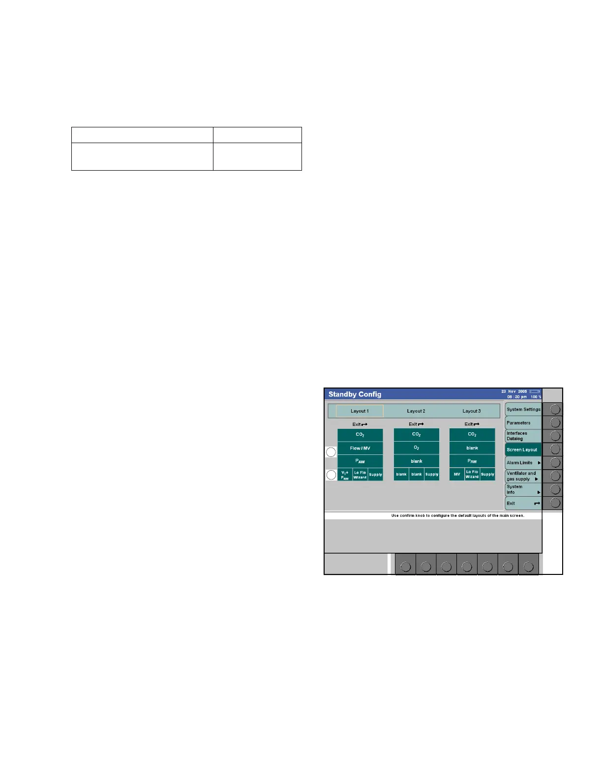
Screen layout
Figure 128. Screen Layout Standby Configuration ScreenThe menu screen layout contains three default
layouts of the home screen: Layout 1, Layout 2, and
Layout 3.
The layouts comprising the following elements which
can be freely configured:
– Three curves with the associated numerical
modules (1 in Figure 128).
The available curves are displayed when a curve
module is selected (1 in Figure 129).
– Three modules which may be assigned to
parameters or status displays (2 in Figure 128).
The available modules are displayed when a
module is selected (1 in Figure 129).
Each curve/module can also be configured as being
blank.
Parameter Factory setting
MEDIBUS V3, MEDIBUS V4,
MEDIBUS.X
MEDIBUS V4

 Loading...