User Interface
48 Instructions for Use Apollo SW 4.5n
Part Number: 9053586, 3rd edition
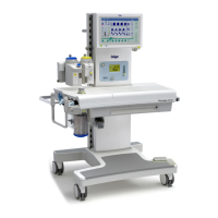
Figure 13. Location of Monitoring/Configuration KeysMonitoring/Configuration control keys
The majority of monitoring and configuration
functions are performed using the vertical column of
buttons along the right side of the screen
(1 in Figure 13). These keys have variable functions
and their labels change according to which
monitoring screen is selected (standard, data, or
trend). An arrow () on the button label indicates
that pressing that key will bring up a second set of
buttons with further user options.
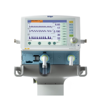
Setting/Selecting Monitoring Functions
Example: change lower alarm limit for etCO
2:
1. Press the button >Alarm Limits<
(2 in Figure 13). The alarm limits menu is
displayed on the screen.
2. Turn the rotary knob to select the low alarm limit
value for etCO
2 (see Figure 14).
Figure 14. Alarm Limits Menu3. Press the rotary knob to confirm the selection.
4. Turn the rotary knob until the desired alarm value
is displayed.
5. Press the rotary knob to confirm the new alarm
limit value.
6. Exit the alarm limits menu by either:
– confirming the close symbol > < with the
rotary knob, or
– pressing the > < key.
Vol . AF
Mode

 Loading...