GE PROPRIETARY TO GE
D
IRECTION 5308917-100, REVISION 8 LOGIQ P3 SERVICE MANUAL
8-42 Section 8-4 - Mechanicals
8-4-6 Caster Wheel Front (FRU P/N :5315118 - LP3, 5368246 - LP3BT10) / Caster Wheel
Rear (FRU P/N: 5315119 - LP3, 5368247 - LP3 BT10)
This is a description on how to remove and replace the castor wheel front and castor wheel rear .
8-4-6-1 Tools
• Common Phillips screwdrivers; Allen Key Set.
8-4-6-2 Needed Manpower
• 1person, 15 minutes each
8-4-6-3 Preparations
• Shutdown the system and switch off the main Circuit Breaker at the bottom rear side of the system.
8-4-6-4 Removal Procedure
1) Remove the Transformer assy. Refer section 8-7-1 on page 76
2) Lift the system slightly up on the side of the castor wheel that needs replacement
3) Place a small block of the size of castor wheel to balance the system
4) Using the allen key set, unfasten the 4 Hex screws holding the Castor wheel and remove it
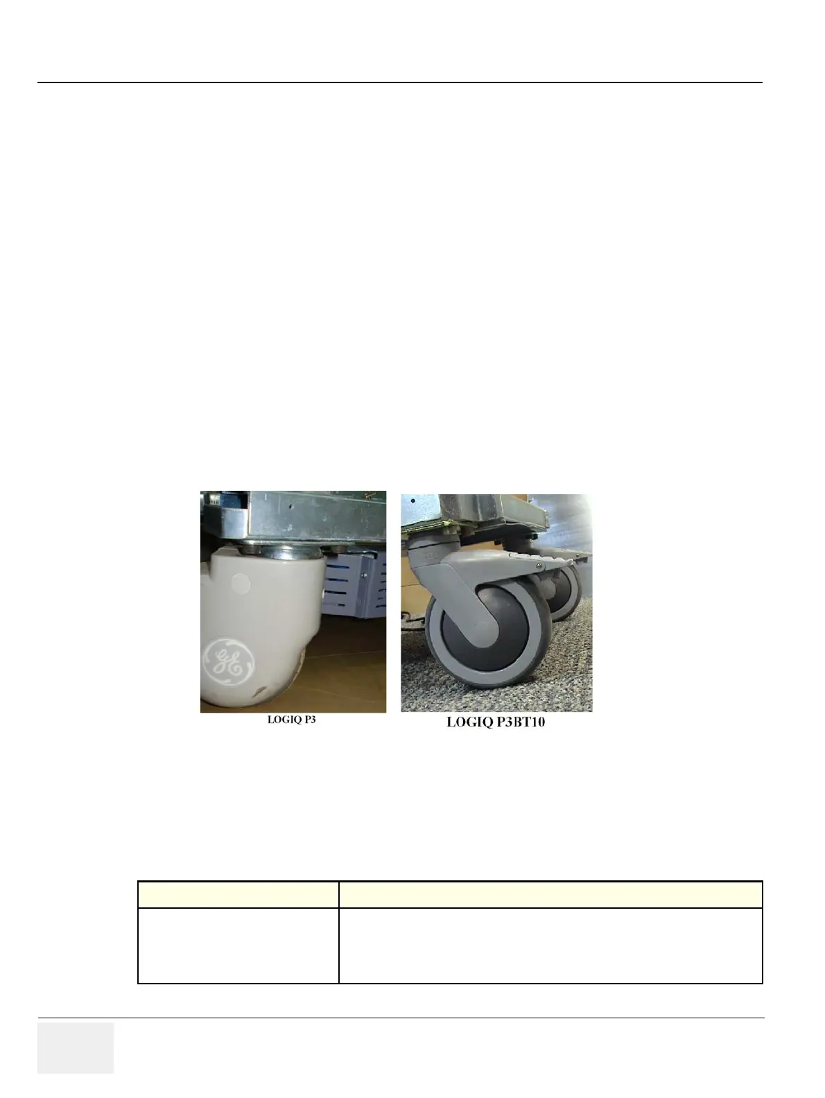
Refer Figure 8-48 on page 8-42
Figure 8-48 Castor wheel
8-4-6-5 Mounting procedure
1.) Install the new parts in the reverse order of removal.
8-4-6-6 Functional Checkout Procedure
Functional Test Debrief Script
Do Visual Inspectionand roll system
around and ensure smooth wheel
rotation and sweivwl
Service Manual Direction 5308917-100, Section 8-4-6. Equipment passes all required
tests and is ready for use.

 Loading...


