GE PROPRIETARY TO GE
D
IRECTION 5308917-100, REVISION 8 LOGIQ P3 SERVICE MANUAL
Chapter 8 Replacement Procedures 8-69
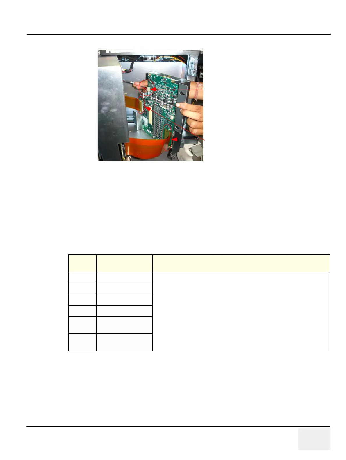
5) Remove the two flexi cable from TX board as shown below
6) To Remove the Flex cable remove one side fron connector board & other side on TX PWA.
7) To remove the TX, remove the 7 fasteners holding TX to RX as shown in Figure 8-79 on page 8-71
8-5-6-5 Mounting procedure
1.) Install the new parts in the reverse order of removal.
8-5-6-6 Functional Checkout Procedure
See
Section Functional Test Debrief Script
4-3-1 Power On/Boot Up
Service Manual Direction 5308917-100, Section 8-6-3. Equipment passes all required
tests and is ready for use.
4-3-2 Power Off/ Shutdown
4-3-6 B Mode Checks
4-3-7 M Mode Controls
4-3-8
Color Flow Mode
Checks
4-3-9
Doppler Mode
Checks
Tx conn board cable
Flex cable

 Loading...


