GE PROPRIETARY TO GE
D
IRECTION 5308917-100, REVISION 8 LOGIQ P3 SERVICE MANUAL
Chapter 8 Replacement Procedures 8-79
8-7-2 Power Block - LOGIQ P3 BT10
8-7-3 Power Entry Module with stickers (FRU No: 5397502), Power Entry Module
Assembly (FRU No. 5268853), Power cord clamp (FRU No: 5389807)
This is a description on how to remove and replace the Transformer Assy.
8-7-3-1 Tools
• Common Phillips screwdrivers
8-7-3-2 Needed Manpower
• 1 persons, 15 minutes
8-7-3-3 Preparations
• Shutdown the system and switch off the main Circuit Breaker at the bottom rear side of the system.
8-7-3-4 Removal Procedure
1) Remove rear cover. Refer section 8-4-3 on page 35. To remove the rear cover, remove the side
covers.
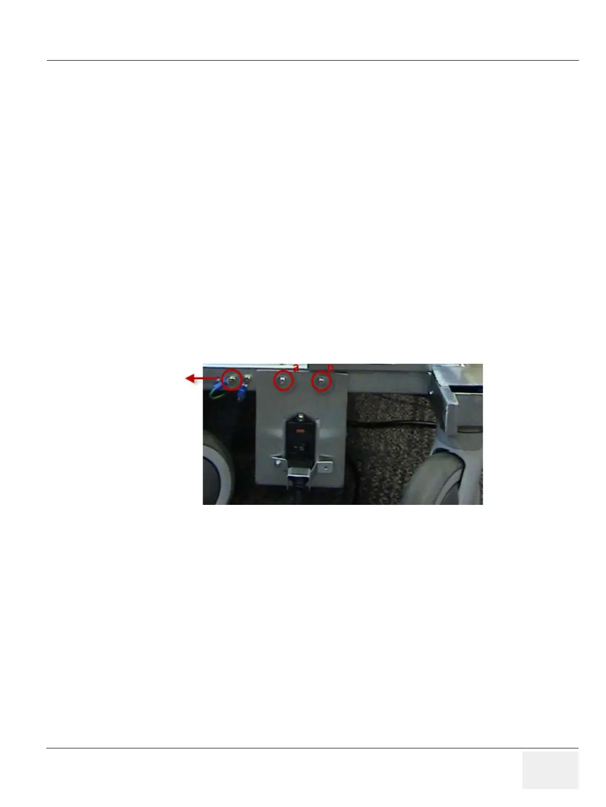
2) Unscrew two screws (a,b) as marked in Figure 8-83 on page 8-76
3) Remove GND cable (which ever connected near to “a” ). Refer Figure 8-83 on page 8-76
Figure 8-86 Removing Transformer Assembly

 Loading...


