
 Loading...
Do you have a question about the GE Voluson P8 and is the answer not in the manual?
| Category | Ultrasound System |
|---|---|
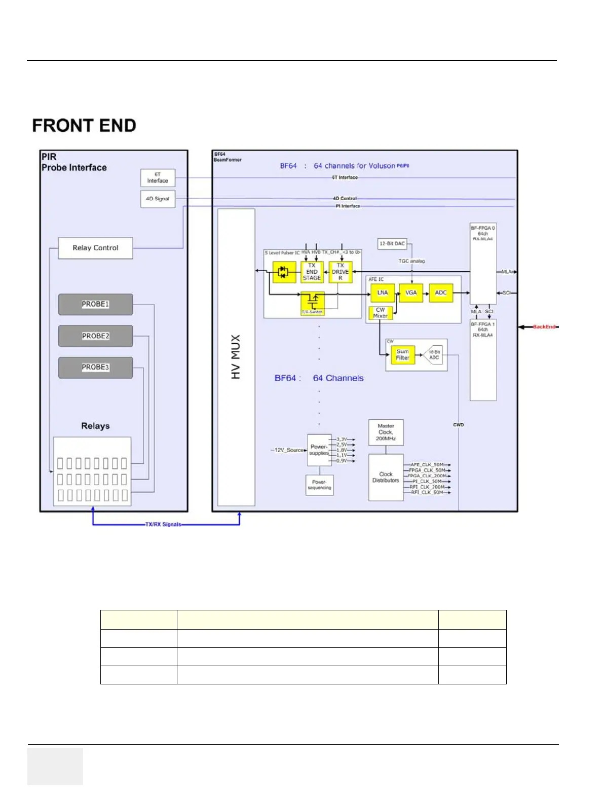
| Probe Ports | 3 active probe ports |
| DICOM | Yes |
| Power Requirements | 100-240 VAC, 50/60 Hz |
| Applications | Obstetrics, Gynecology |
| Imaging Modes | Color Doppler, Power Doppler |
| Connectivity | Ethernet, USB |
| Operating System | Windows-based |


