GE HEALTHCARERAFT VOLUSON® P8 / VOLUSON® P6
DIRECTION 5459672-100, R
EVISION 6 DRAFT (JANUARY 17, 2013) PROPRIETARY SERVICE MANUAL
10-28 Section 10-8 - Electrical Safety Tests
10-8-10 Type BF Patient Leakage current - Mains to Probe
Reference the procedure in the IEC 60601-1.Measure leakage current flow from mains to Probe.
10-8-11 Type CF Patient Leakage current - Mains to ECG lead
Reference the procedure in the IEC 60601-1.Measure leakage current flow from mains to each of the
ECG leads.
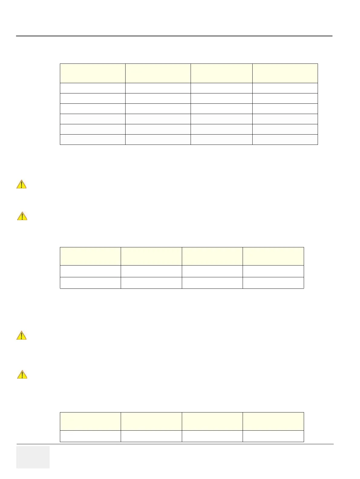
Table 10-29 Typical Data Sheet for Type CF Patient Leakage Current - Mains to ECG Lead
Table 10-27 Typical Data Sheet for Type BF Patient Auxiliary Current Test
Tester Neutral Tester Polarity Switch Ground Switch
Measured Leakage
Current
Closed Normal Closed
Closed Normal Open
Closed Reversed Closed
Closed Reversed Open
Open Normal Closed
Open Reversed Closed
DANGER
!! DANGER:
Electric Shock Hazard.
Line voltage is applied to Probe during this test. To avoid possible electric shock hazard, the
system being tested must not be touched by patients, users or anyone during testing.
CAUTION
!! CAUTION:
Equipment damage possibility. Never switch the Polarity and the status of Neutral when the unit
is powered ON. Be sure to turn the unit power OFF before switching them using the POLARITY
switch and/or the NEUTRAL switch. Otherwise, the unit may be damaged.
Table 10-28 Typical Data Sheet for Type BF Patient Leakage Current - Mains to Probe
Tester Neutral Tester Polarity Switch Ground Switch
Measured Leakage
Current
Closed Normal Closed
Closed Reversed Closed
DANGER
!! DANGER:
Electric Shock Hazard.
Line voltage is applied to the ECG leads during this test. To avoid possible electric shock
hazard, the system being tested must not be touched by patients, users or anyone during
testing.
CAUTION
!! CAUTION:
Equipment damage possibility. Never switch the Polarity and the status of Neutral when the unit
is powered ON. Be sure to turn the unit power OFF before switching them using the POLARITY
switch and/or the NEUTRAL switch. Otherwise, the unit may be damaged.
Tester Neutral Tester Polarity Switch Ground Switch
Measured Leakage
Current
Closed Normal Closed

 Loading...


