GE HEALTHCARERAFT VOLUSON® P8 / VOLUSON® P6
DIRECTION 5459672-100, R
EVISION 6 DRAFT (JANUARY 17, 2013) PROPRIETARY SERVICE MANUAL
7-40 Section 7-9 - Hardware Tests
7-9-6-1 System Overall Test
System Overall Test is root-top level test that executes all the sub diagnostic tests. It executes each sub
diagnostic test one by one, and summarizes the test result at the end of the test execution.
7-9-6-2 RFS Overall Test
This diagnostic test performs the self-diagnosis of each electric component and interface in the RFS
board.
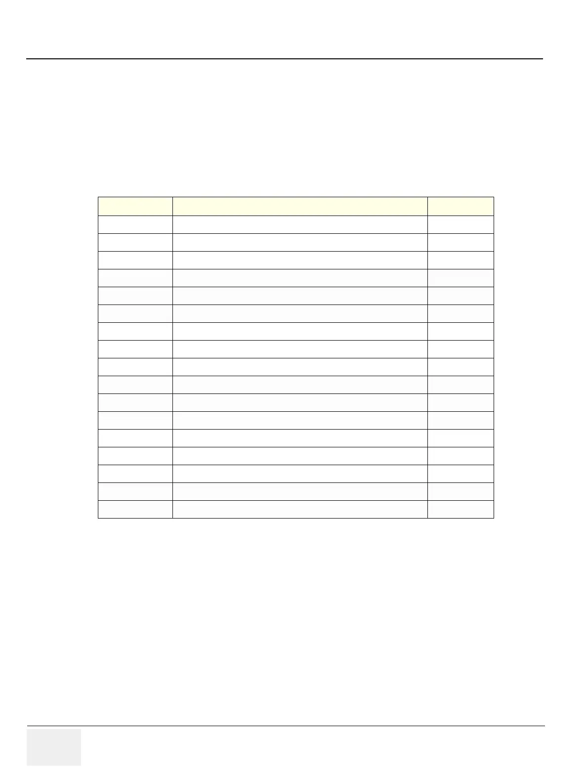
Table 7-3 below outlines Voluson® P8 / Voluson® P6 Diagnostics Tool described in the sub-sections.
7-9-6-2-1 Voltage Test
It verifies Each Power Voltage Level on RFS board, and displays the current voltage levels and the test
result as PASSED/FAILED.
7-9-6-2-2 PCIE Interface Test
It verifies PCIe Interface between SOM and PEX8112 chip on RFS board, and displays the test result
as PASSED/FAILED.
7-9-6-2-3 PCI Interface Test
It verifies PCI bus interface between PEX8112 and PCI9054 on RFS board, and displays the test result
as PASSED/FAILED.
7-9-6-2-4 LocalBus I/O Test
It verifies PCI LocalBus between PC9054 and FPGA on RFS board, and displays the test result as
PASSED/FAILED.
Table 7-3 Automatic diagnostic test under RFS Test
Sub-section Description Page Number
7-9-6-2-1
Voltage Test
7-40
7-9-6-2-2
PCIE Interface Test
7-40
7-9-6-2-3
PCI Interface Test
7-40
7-9-6-2-4
LocalBus I/O Test
7-40
7-9-6-2-5
FPGA(RFS) Configuration Test
7-41
7-9-6-2-6
BF Coef RAM Test
7-41
7-9-6-2-7
Scan Seq RAM Test
7-41
7-9-6-2-8
Mid Coeff RAM Test
7-41
7-9-6-2-9
DeInterleave RAM Test
7-41
7-9-6-2-10
Line Memory DMA Test
7-41
7-9-6-2-11
CLK Test
7-41
7-9-6-2-12
Serial DAC Interface Test
7-41
7-9-6-2-13
IIC(Local) Interface Test
7-41
7-9-6-2-14
VPD(RFS) Test
7-41
7-9-6-2-15
HW ID Test
7-41
7-9-6-2-16
Temperature Read Test
7-41
7-9-6-2-17
Vsync missing Test
7-41

 Loading...


