GE HEALTHCARERAFT VOLUSON® P8 / VOLUSON® P6
DIRECTION 5459672-100, R
EVISION 6 DRAFT (JANUARY 17, 2013) PROPRIETARY SERVICE MANUAL
7-44 Section 7-9 - Hardware Tests
7-9-6-5-2 IIC(CPS) Interface Test
It verifies I2C path named I2C_PS by using EERPOM on CPS board, and displays the test result as
PASSED/FAILED.
7-9-6-5-3 VPD(CPS) Test
It verifies VPD Information embedded in EEPROM on CPS board, and displays the part of VPD
information and the test result as PASSED/FAILED.
7-9-6-5-4 ADM Test
It verifies the interface to ADM1062 chip on CPS board by reading/writing test data, and displays the
test result as PASSED/FAILED.
7-9-6-5-5 HV Linearity Test
It verifies the linearity of HVA and HVB voltage by writing test voltage and reading back corresponding
voltage, and displays the written and read voltage in log window, and the test result as PASSED/
FAILED.
7-9-6-5-6 HV Stop Function Test
It verifies ADM operation when HV_Stop is asserted whether HVA/HVB outputs 0V, and displays the
current voltage changes and the test result as PASSED/FAILED.
7-9-6-6 DC4D Overall Test
This diagnostic test performs the self-diagnosis of each electric component and interface on DC4D
board.
Table 7-7 below outlines Voluson® P8 / Voluson® P6 Diagnostics Tool described in the sub-sections.
7-9-6-6-1 VPD(DC4D) Test
It verifies VPD Information embedded in EEPROM on DC4D board, and displays the part of VPD
information and the test result as PASSED/FAILED.
7-9-6-7 Channels Overall Test
This diagnostic test performs the self-diagnosis of channel related test from FrontEnd and BackEnd.
Table 7-8 below outlines Voluson® P8 / Voluson® P6 Diagnostics Tool described in the sub-sections.
7-9-6-7-1 ASP(Analog Signal Path) Test
It verifies ASP(Analog Signal Path) from AFE to RFS by generating test wave signal and recording it
with ADC, and displays each channels diagnostic result, and the overall test result as PASSED/FAILED.
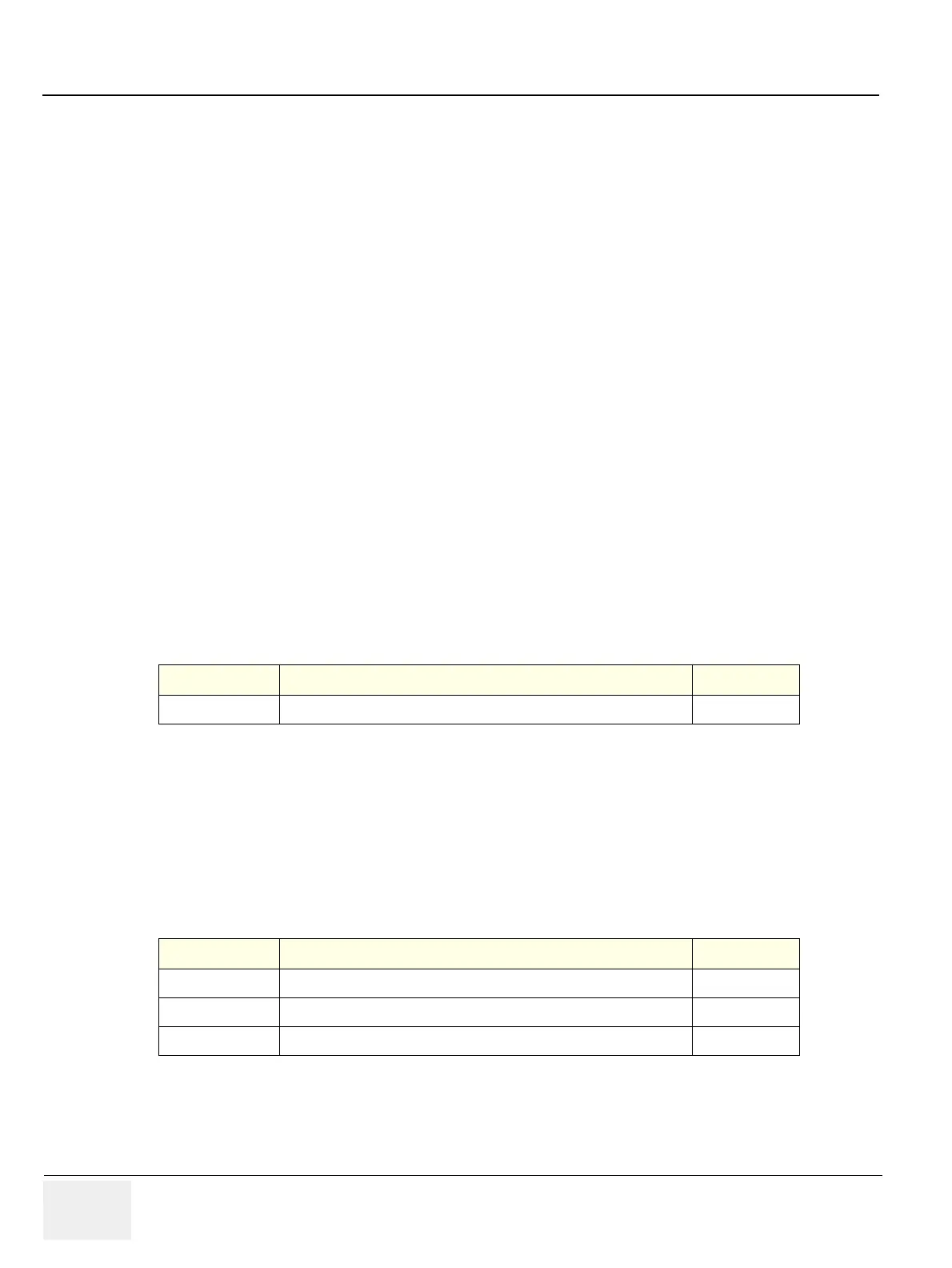
Table 7-7 Automatic diagnostic test under DC4D Test
Sub-section Description Page Number
7-9-6-6-1
VPD(DC4D) Test
7-44
Table 7-8 Automatic diagnostic test under Channel Test
Sub-section Description Page Number
7-9-6-7-1
ASP(Analog Signal Path) Test
7-44
7-9-6-7-2
Tx Signal Path Test
7-45
7-9-6-7-3
CW Signal Path Test
7-45

 Loading...


