1. Check the labels on the support rails. Each rail has a label that indicates which is the front end of the
rail and whether the rail is for the left or right side of the rack. Perform this procedure for both rails.
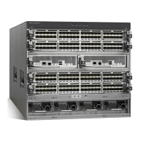
2. Put your index finger against the side of the latch-lever, 1 in Figure 60, and put your thumb
against the front of the latch-lock 2.
1 Latch lever
2 Latch lock
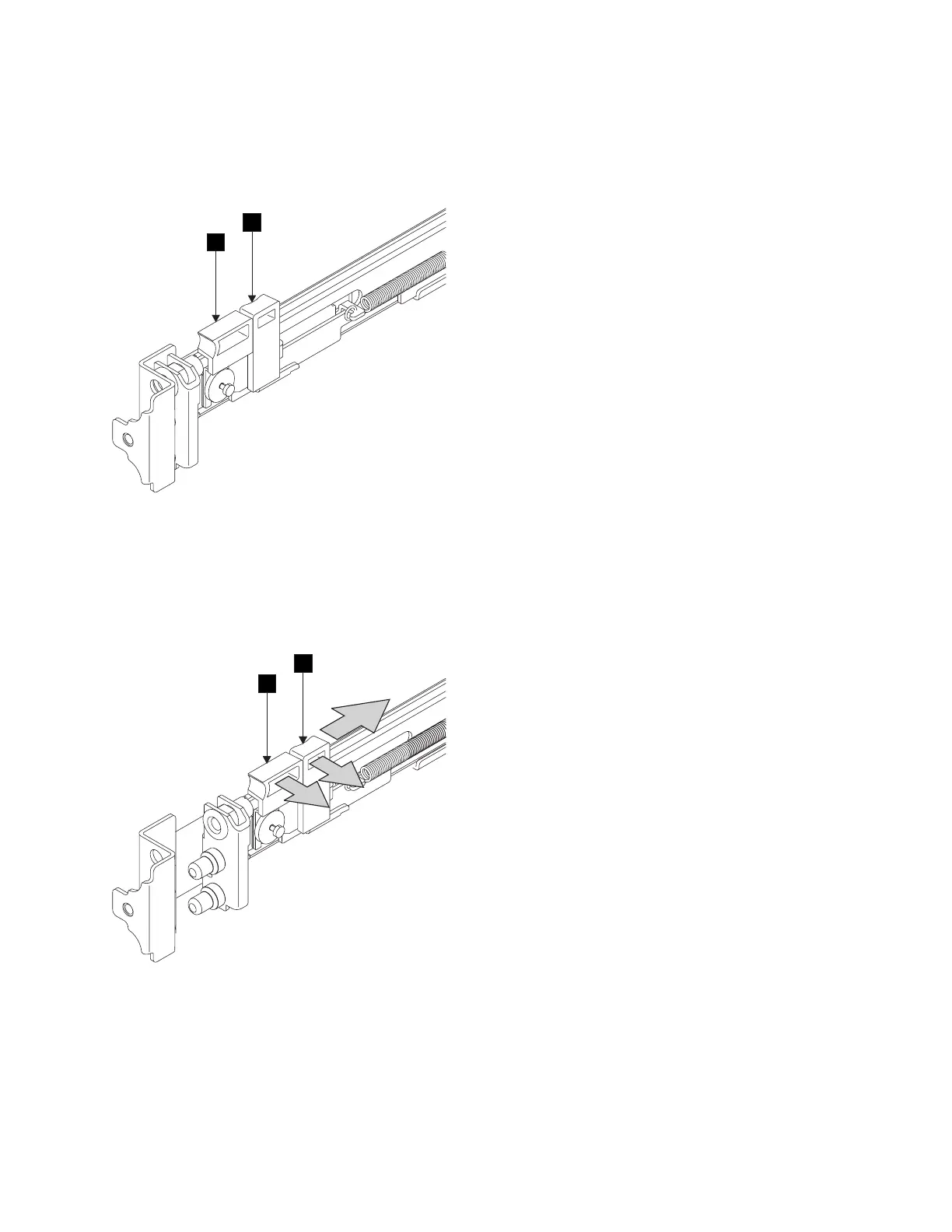
3. Gently push the latch lock 2 away from the rail as you move the latch lever 1 toward the far
end of the rail (Figure 61). The latch-lock carrier assembly slides against the spring tension.
1 Latch lever
2 Latch lock
4. Continue to slide the latch-lock carrier for approximately 13 mm (0.5 in). The latch-lever engages a
hole in the back bracket assembly and holds the latch-lock carrier in the retracted position.
1
2
Figure 60. Retracting the latch-lock carrier
1
2
1
2
23nl1c
Figure 61. Opening the front latch-lock carrier assembly
Chapter 2. Removing and replacing parts 75
 Loading...