1. Turn off the node while ensuring that its data is mirrored and synchronized. See MAP 5350 in the
IBM System Storage SAN Volume Controller Troubleshooting Guide for more information.
2. Remove the top cover. See “Removing the top cover” on page 77.
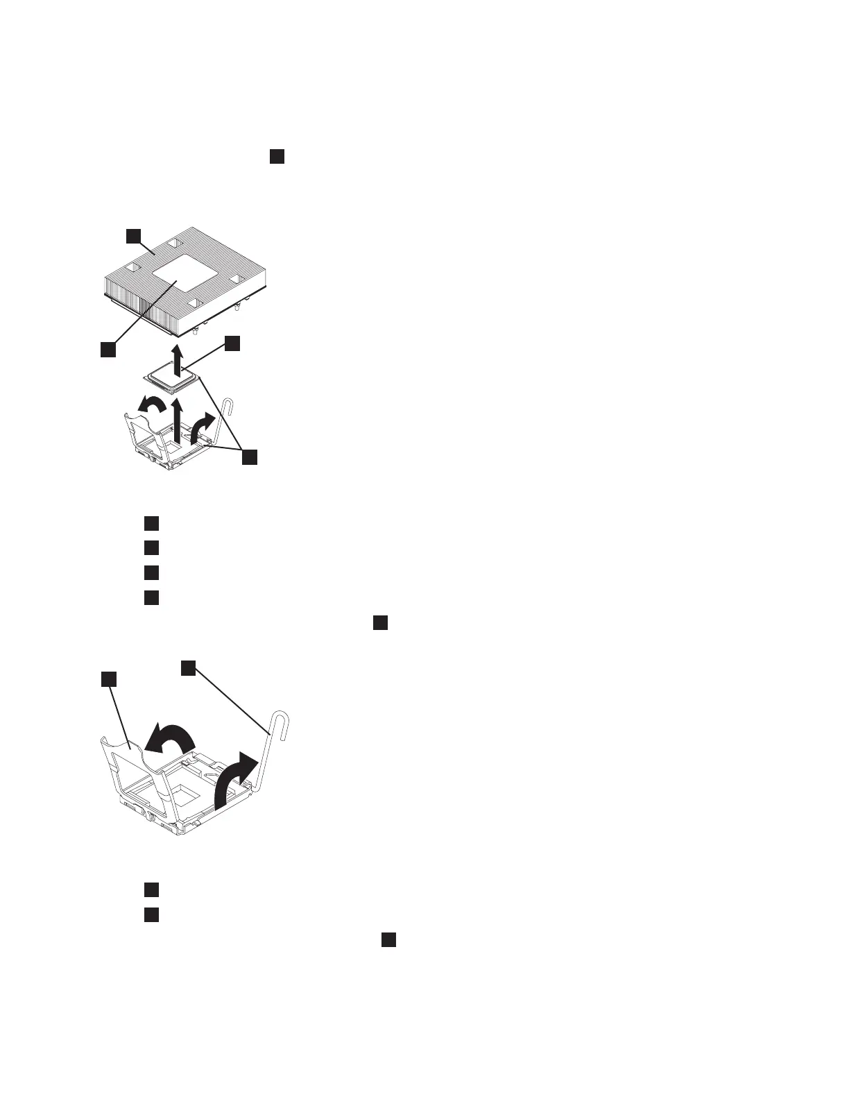
3. Remove the heat sink (
1
in Figure 256). Loosen two captive screws on alternate sides of the heat
sink fully before loosening the other two captive screws. (This helps to break the bond between the
heat sink and the microprocessor.) After the captive screws are loosened, remove the heat sink.
1
Heat sink
2
Heat sink installation label
3
Microprocessor
4
Alignment indicator
4. Open the microprocessor release lever (
1
in Figure 257) to the fully open position.
1
Microprocessor release lever
2
Microprocessor bracket frame
5. Open the microprocessor bracket frame (
2
in Figure 257).
6. Carefully remove the microprocessor from the socket. Be careful to only touch the edges of the
microprocessor.
svc00285
1
3
4
2
Figure 256. Removing the heat sink from the microprocessor
1
2
svc00288
Figure 257. The microprocessor release lever and bracket frame fully opened
Chapter 2. Removing and replacing parts 257
 Loading...